AASD chinese ac servo's step/dir Oscilations
- bevins
-
 Topic Author
- Offline
- Platinum Member
-

- Posts: 1942
- Thank you received: 338
These seem to be the relevant parameters:
Pn045 - Gain switching selection (0-5, set to 0 for "Fixed first gain")
Pn257 - Load inertia ratio (0-100)
Pn258 - Gain adjustment mode (0-1, set to 0 for manual gain adjustment)
Pn196 - Torque filtering time constant (1-5000, unit 0.01 ms)
Pn153 - Speed loop gain (1-2000, unit 1 Hz)
Pn154 - Speed loop integral time constant (1-5000, unit 0.1 ms)
Pn115 - Position loop gain (1-2000, unit 1 Hz)
Pn184 - Speed feedback compensation
(There is no D component, but the manual suggests ways to combat jitter/vibration in section 8.3.4.)
What are these set to in your drives?
I have been through changing all these values and what ever I set them at I get either violent oscillations or it just sits there making loud noises.
I will get these settings tonight when I go back to the shop.
This puts it in a different perspective than I was looking at. Thanks,
One thing to note, whether it is in step/direction or analog +-10v it does basically the same thing.
The one way to bypass the internal pid loop I couldn't get 100%. Setting sp1 sp2 sp3 to get the 000 binary didnt make sense. IT is quite confusing this manual.
Please Log in or Create an account to join the conversation.
- bevins
-
 Topic Author
- Offline
- Platinum Member
-

- Posts: 1942
- Thank you received: 338
Also works great connected to the drive when jogging from the drive.
Please Log in or Create an account to join the conversation.
- bevins
-
 Topic Author
- Offline
- Platinum Member
-

- Posts: 1942
- Thank you received: 338
These seem to be the relevant parameters:
Pn045 - Gain switching selection (0-5, set to 0 for "Fixed first gain") Set to 0 fixed gain #1
Pn257 - Load inertia ratio (0-100) 65, as set from inertia test function,
Pn258 - Gain adjustment mode (0-1, set to 0 for manual gain adjustment) tried both, when set for manual gain tried adjusted as laid out in manual. in set to 1 tried all the different settings.
Pn196 - Torque filtering time constant (1-5000, unit 0.01 ms) 40 tried up to 1500
Pn153 - Speed loop gain (1-2000, unit 1 Hz) 140
Pn154 - Speed loop integral time constant (1-5000, unit 0.1 ms) 180
Pn115 - Position loop gain (1-2000, unit 1 Hz) 100
Pn184 - Speed feedback compensation 0, wont let me change it.
Here are the settings.
(There is no D component, but the manual suggests ways to combat jitter/vibration in section 8.3.4.)
What are these set to in your drives?
Please Log in or Create an account to join the conversation.
- PCW
-

- Offline
- Moderator
-

- Posts: 17404
- Thank you received: 5070
One thing to note, whether it is in step/direction or analog +-10v it does basically the same thing.
That suggests that the tuning issue is in the velocity (or perhaps torque) loop
Please Log in or Create an account to join the conversation.
- bevins
-
 Topic Author
- Offline
- Platinum Member
-

- Posts: 1942
- Thank you received: 338
Have you checked that "Automatic gain adjustment mode" isn't enabled (Pn258=1)?
According to page 196 in the manual, "8.3.2 Automatic gain adjustment", if you have Pn258 = 1 then "gain parameters such as Pn115, Pn116, Pn153~P156, Pn196, and Pn197 are not valid".
I tried the auto and manual.
Please Log in or Create an account to join the conversation.
- bevins
-
 Topic Author
- Offline
- Platinum Member
-

- Posts: 1942
- Thank you received: 338
One thing to note, whether it is in step/direction or analog +-10v it does basically the same thing.
That suggests that the tuning issue is in the velocity (or perhaps torque) loop
Does it run through the speed and torque loop while in step and dir mode?
Please Log in or Create an account to join the conversation.
- arvidb
-

- Offline
- Platinum Member
-

- Posts: 459
- Thank you received: 157
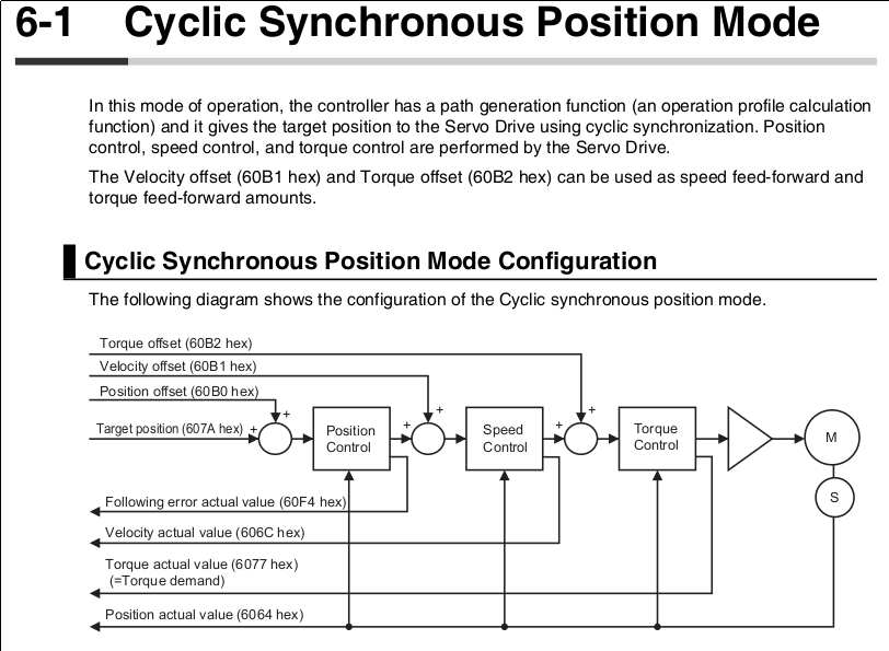
Yes. Velocity mode uses velocity and torque loops; position control (step/dir) uses position, velocity, and torque loops. The position loop sends a velocity command to the velocity loop, which in turn sends a torque command to the torque filter.Does it run through the speed and torque loop while in step and dir mode?
The Omron G5 manual states that if hunting occurs in position control mode, one should decrease speed loop gain and increase speed loop integral time constant (pp 11-16, page 474).
Please Log in or Create an account to join the conversation.
- arvidb
-

- Offline
- Platinum Member
-

- Posts: 459
- Thank you received: 157
And here's some notes from Wikipedia on cascade control: link .
Attachments:
Please Log in or Create an account to join the conversation.
- bevins
-
 Topic Author
- Offline
- Platinum Member
-

- Posts: 1942
- Thank you received: 338
I am biting the bullet buying new servos and drives this week.
Probably going with DYN4's. This is coming right out of my pocket.
Kind of sucks but I know I am rolling the dice buying from china. Lesson learned.
What sucks is I have bought these in the past and made them work great.
Please Log in or Create an account to join the conversation.
- DEVILHUNTER
- Offline
- Junior Member
-

- Posts: 30
- Thank you received: 10
I have some of this chinese servos. My drivers are not exactly the same, but the manual sent by the shop is the same. Mines seems to be a little newer design named A1-SVD15 instead of AASD15, with two RJ45 ports (seller said it could be used by EtherCAT but I'm reluctant about that statment, will try on the Rpi4). It's a shame there is no actual manual for this drives, because I'm pretty sure I'm missing some functionalities.
The first manual I got was the 6.1 version, Got them kinda tunned in position mode by setting a fixed automatic gain (Pn258 = 1, Pn259 = 4) and playing with the inertia ratio (Pn257). I could move a little the saft by hand and they had some delay following the path, but was OK enough for me and been working for a year this way.
In the meanwhile got the 6.3 version manual that Bevins has sent and It was way more complete. So yesterday decided to improve the tunning and I'm going to explain what I did because I think it will be usefull for people as there is pretty little info about this servos. I'm not going to enter in basic parameter settings, like servo enable, electronic gearing and so on, but if anyone needs it just ask for them.
First I did the math to calculate the theorical load-inertia ratio between my machine and each motor. This video is pretty usefull:
Then feed the parameters needed to perform the automatic inertia ratio guessing procedure. The first two I set them trying to get the same acceleration that I have set in the INI file. It's smaller but should work.
Pn263 = 20 (acceleration and deceleration time during the procedure)
Pn264 = 1000 (máx rpm during the procedure)
Pn265 = 500 (puase during the procedure)
Pn266 = the inertia ratio I calculated, 2 for X, 1.23 for Y and 1 for Z
Pn267* = nominal torque of the servo in 0.1 N·mu nits. So 19.3 and 23.9 as my servos have 1.93 and 2.39 N·m
Pn268* = max torque of the servo in 0.1 N·m units. So 19.3 and 23.9 as my servos have 1.93 and 2.39 N·m
Pn269* = servo rotor inertia in 0.0001 units. So 0.39 and 1.8 for my servos
Pn270* = no idea what it does, maybe reduce the motor current
Pn271* = 3000 (max motor speed)
I have marked some of the parameters with a (*) because there are inconsistencies in the manual. On page 140 says that Pn270 is the max speed, but this parameter only goes to 100 so Pn271 is the real max speed as stated in page 65. Pn267 and Pn268 are marked in 0.1 N·m in the page 140, but in page 65 Pn267 is in N·m and Pn268 in percentage. I have not checked this but will do this afternoon, if Pn268 only goes up to 300 means it's on percentage. The order of magnitude is also more consistent with the page 65. Pn269 has also different max values.
Now the servo has to be disconected on the enable, either by turning the external enable pin down or by setting Pn003 to 0. Go to function Fn018 in the servo and press set a couple of times to start the automatic inertia ratio procedure. The machine now will start moving a little and showing in the display the inertia ratio calculated. On my case the movements were crisp and the value didn't showed a lot of variance so that was a great signal.
The inertia ratio I got was consistent with the ones I calculated, 2.65 for X, 0.7 for Y and 0.8 for Z. Now feed this values into the Pn257 of each servo.
Now make sure the driver is in automatic gain adjustment (Pn258 = 1) and start with a lower rigid grade (Pn259). I started with 4 but if your machine is not rigid. Enable again the machine and do some jogging. If it goes smooth, increase the Pn259 by 1 and check again. Once the machine shows an unstable condition where the servo oscilates, backed up a couple of grades of the Pn259 to make sure it was on a safe grade.
With all if this the movents on my machine were super crisp, with no visible overshoot or delay on the moovments. The saft was also really rigid and I could not move it by hand like before. I was REALLY happy. Machined one part and turned down the machine with everything OK.
Today I powered up the machine and pressed the home all in LinuxCNC and that's were my problems started really bad! All the servos went unstable with high oscilations, my machine violent shaking and almost walked ot of my workshop until I could press the e-stop.
I'm runing a MESA 7i76e but I'm pretty sure my problem is not related with LinuxCNC at all. With the computer disconected if I know out of position the servos they get unstable again.
At first I thought It could be that my machine was cold but when I did the tunning it wasn't really warmed either. Also changed the parameters to get them as they were before but now the machine gets really slower, plus a lot of overshoot. Even a overspeed alarm on X, really weird.
Disconected all servos but one, to make sure the coolant have not messed anything electrical, and did more testing. If I repeat the inertia ratio guessing procedure now I get values around 20, that make no sense at all.
Don't think is anything mechanical as I cannot feel any play at all, but will check the preloads again just in case.
The drivers could get desconfigurated when I turned them down but I have checked that all the parameters I changed had the same value I left them with. It's really weird that all axis have failed at the same time.
I'm really lost right now. Will try to get the drivers into the factory settings and start again.
Please Log in or Create an account to join the conversation.

