linuxcnc trajectory planner
- Aciera
-

- Offline
- Administrator
-

Less
More
- Posts: 4646
- Thank you received: 2067
13 Oct 2024 05:39 - 13 Oct 2024 06:44 #311929
by Aciera
[edit]
It might be a good idea to exclude the difficult cases for now. There are likely others, like where the gcode execution depends on input during runtime (eg where probing is run during gcode execution).
Replied by Aciera on topic linuxcnc trajectory planner
Certainly an important function (at least on some machines) but likely does not need optimization. Problem might be that the end position is not known before it is actually executed (I think).How important is rigid tapping for the planner?
[edit]
It might be a good idea to exclude the difficult cases for now. There are likely others, like where the gcode execution depends on input during runtime (eg where probing is run during gcode execution).
Last edit: 13 Oct 2024 06:44 by Aciera.
The following user(s) said Thank You: Grotius
Please Log in or Create an account to join the conversation.
- juliankoenig87
- Offline
- Premium Member
-

Less
More
- Posts: 119
- Thank you received: 55
13 Oct 2024 07:36 #311936
by juliankoenig87
Replied by juliankoenig87 on topic linuxcnc trajectory planner
While probing its also important to have predictable decceleration distances. Otherwise it is not easy to implement safety functions.
Im not sure where to place my thoughts. So maybe its wrong in this thread.
Best regards
Julian
Im not sure where to place my thoughts. So maybe its wrong in this thread.
Best regards
Julian
The following user(s) said Thank You: Grotius
Please Log in or Create an account to join the conversation.
- Grotius
-
 Topic Author
- Offline
- Platinum Member
-

Less
More
- Posts: 2419
- Thank you received: 2345
14 Oct 2024 00:47 - 14 Oct 2024 01:20 #312016
by Grotius
Replied by Grotius on topic linuxcnc trajectory planner
@Arciera,
For me it's not entirely clear how the probing flow is done, didn't look at is so far.
We will not invest time in it for now, exclude it for now.
@Julian,
While probing its also important to have predictable decceleration distances.
I don't get it.
Im not sure where to place my thoughts. So maybe its wrong in this thread.
Your thoughts are welcome.
Edit:
We are now at the stage that the trajectory is filletized with 3d bspline's.
For the 3d bspline's i used a lib called tinyspline , instead of linking to the huge opencascade lib.
Ok next step should ideally be visualizing the trajectory including the fillet result. But how?
We didn't coded the plannet yet. And the original planner can not run the fillets.
1. For this i could create a tiny tpmod_viewer.so component (helper component) wich draws the yellow toolpath line over the gcode path.
2. Modify the original planner, to also run spline fillets. This includes logic to reload the lcnc gcode queue at runtime. More difficult.
3. Create a text file output with trajectory points every mm to load into a external online viewer.
What should we do? Any thoughts about validating the filletized trajectory path?
Last edit: 14 Oct 2024 01:20 by Grotius.
The following user(s) said Thank You: akb1212, pommen, Lcvette, Aciera
Please Log in or Create an account to join the conversation.
- juliankoenig87
- Offline
- Premium Member
-

Less
More
- Posts: 119
- Thank you received: 55
14 Oct 2024 05:15 #312031
by juliankoenig87
Hi.
Probes have a specific way to go, before they break. I use this distance to calculate a max velocity while probe operations. For this I use usually fixed accelaration values. Of course debounce times and so on also.
If there will be non predictable acceleration values, or better non predictable distances right now I would struggle to implement such safety checks.
Attached my safety check for easyprobe.
Replied by juliankoenig87 on topic linuxcnc trajectory planner
Hi.
Probes have a specific way to go, before they break. I use this distance to calculate a max velocity while probe operations. For this I use usually fixed accelaration values. Of course debounce times and so on also.
If there will be non predictable acceleration values, or better non predictable distances right now I would struggle to implement such safety checks.
Attached my safety check for easyprobe.
Attachments:
The following user(s) said Thank You: Grotius
Please Log in or Create an account to join the conversation.
- Aciera
-

- Offline
- Administrator
-

Less
More
- Posts: 4646
- Thank you received: 2067
14 Oct 2024 07:20 #312040
by Aciera
I would just go for the easiest solution for now. Once we see that the optimization actually works we can still think about a better preview solution.
Replied by Aciera on topic linuxcnc trajectory planner
What should we do? Any thoughts about validating the filletized trajectory path?
I would just go for the easiest solution for now. Once we see that the optimization actually works we can still think about a better preview solution.
The following user(s) said Thank You: Grotius
Please Log in or Create an account to join the conversation.
- automata
- Offline
- Premium Member
-

Less
More
- Posts: 95
- Thank you received: 73
14 Oct 2024 09:30 #312048
by automata
Replied by automata on topic linuxcnc trajectory planner
Hi Grotius,
Glad to see you are back at this.
For Probing and Spindle Synchronized motion, the use cases do not admit blending. For both we can have the current default behaviour enabled. That will help move things along.
Spindle sync can be done with arc blending as is being done today. The first sync move generally starts from zero velocity and also ends at zero velocity.
For Probing, the start velocity can be assumed to be zero and the end velocity is always zero. (With zero velocity at any end of a segment, we don't need to blend that end.)
For the visualization of the filletized trajectory path, we can start with whatever is straight forward and easy. A separate visualizer which takes input from the terminal output of the trajectory optimization module will also work.
Let me know if you want to test with the Ethercat servo and stepper motor/drives and we can figure out how to ship them out to you.
Eagerly looking forward to the successful integration of this work and trying it out on my mill.
-automata
The following user(s) said Thank You: akb1212, Grotius, tiagounderground, Unlogic
Please Log in or Create an account to join the conversation.
- Grotius
-
 Topic Author
- Offline
- Platinum Member
-

Less
More
- Posts: 2419
- Thank you received: 2345
15 Oct 2024 00:03 #312115
by Grotius
Replied by Grotius on topic linuxcnc trajectory planner
Hi Guys,
Thanks for your responce's.
@Automata, when time is ready, will check you back for the servo's. I think that's nice to have around here.
We have some results today.
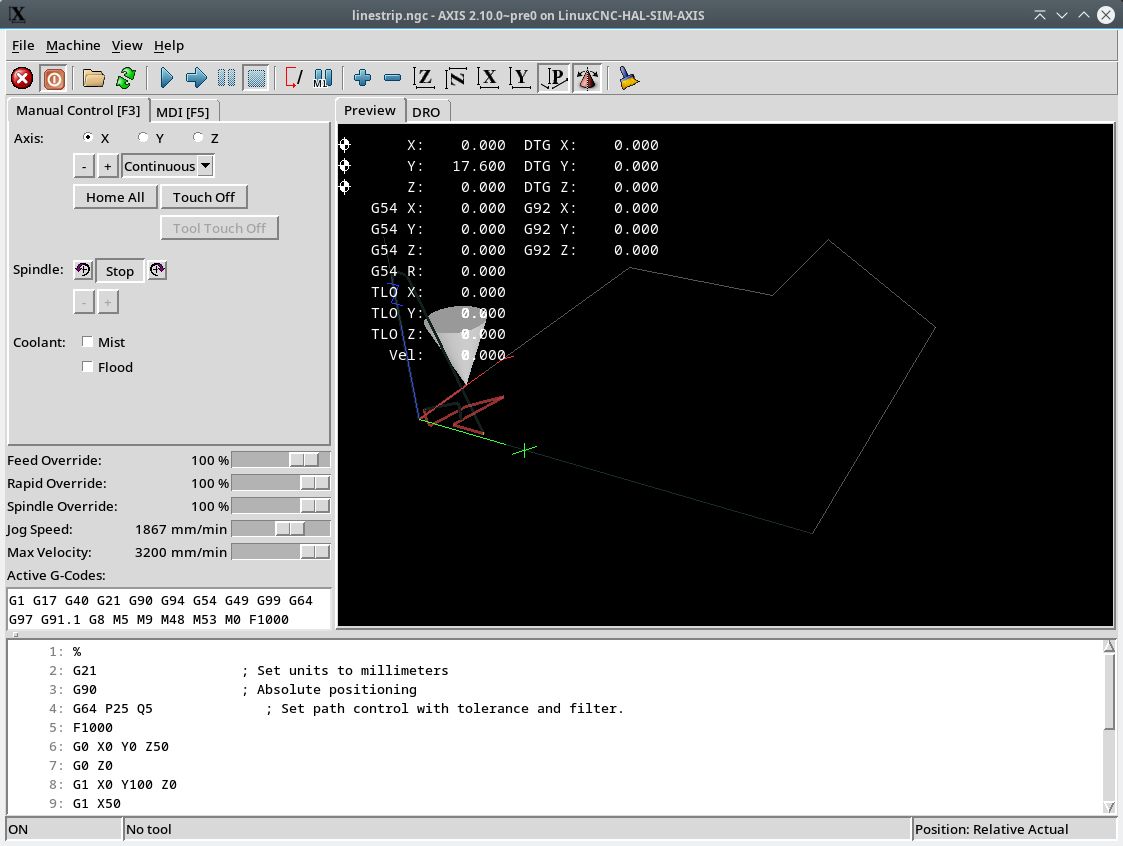
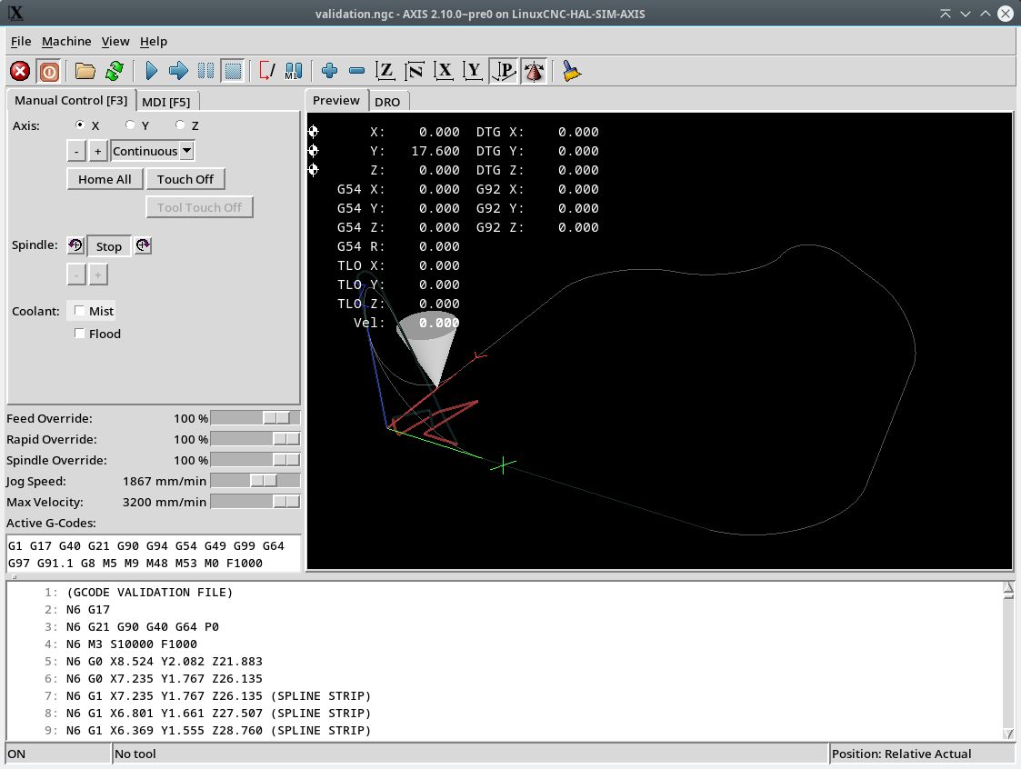
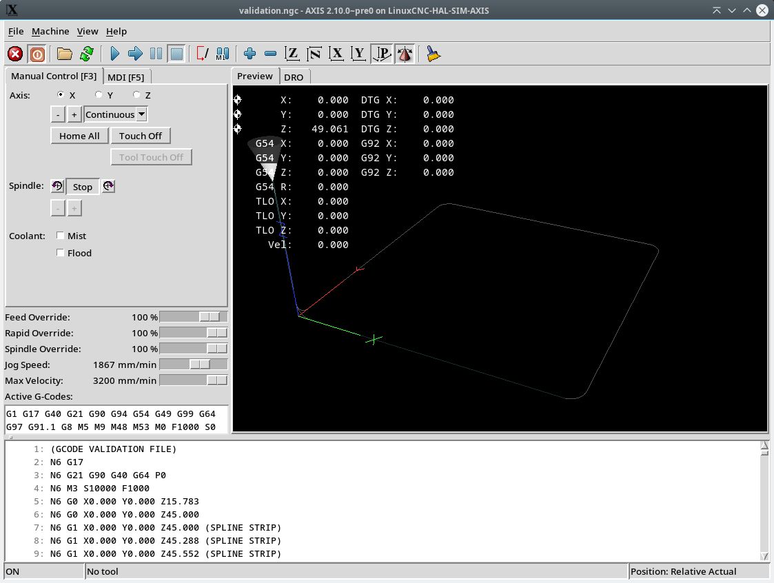
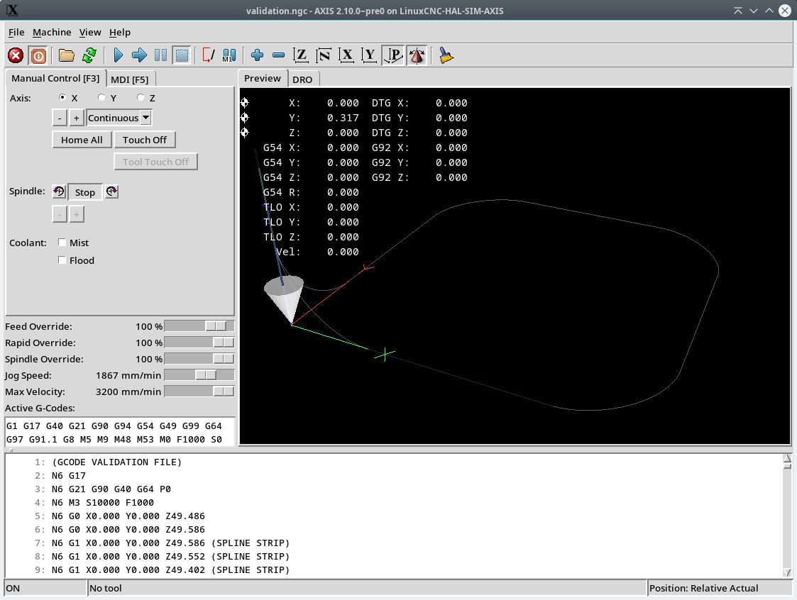
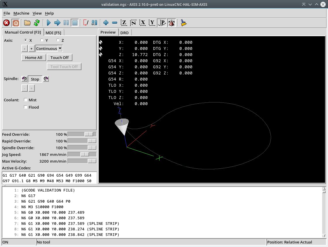
When the buffer is loaded and path is optimized, it writes a gcode file named "validation.ngc" into the ~/cmake dir.
Then you can load this file into lcnc and check results.
Some times the path optimalisation fails. So have to look what's going on.
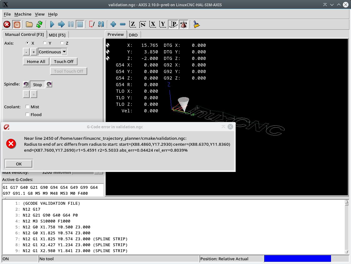
I have to dive deeper into the original lcnc circle math. As this gives sometimes error's at lcnc runtime.
The message is like "arc radius differs ..." Most of time around 1.4%.
It's now late. Will check some things tommorow.
Attached some test pictures. I used also chamfer fillets for test. And bsplines.
The following user(s) said Thank You: akb1212, tommylight, Lcvette, Darium
Please Log in or Create an account to join the conversation.
- Grotius
-
 Topic Author
- Offline
- Platinum Member
-

Less
More
- Posts: 2419
- Thank you received: 2345
15 Oct 2024 10:06 #312140
by Grotius
Replied by Grotius on topic linuxcnc trajectory planner
Hi,
G64 P0. Showing the original.
G64 P25 Showing the bspline blend.
G64 P5 Original this is a square.
G64 P25
G64 P50
So far it looks the bpsline fillets for attached line's are working fine.
However, for circles, we got this error :
I used the lcnc math to interpolate the circle at a given progress 0-1.
Now the result is used as arc point in the gcode, this should be ok.
So i have to look what is going on.
So far so good. We got already some results that looks like a bspline fillet.
updated repositiry
The following user(s) said Thank You: akb1212, Lcvette, Darium
Please Log in or Create an account to join the conversation.
- juliankoenig87
- Offline
- Premium Member
-

Less
More
- Posts: 119
- Thank you received: 55
15 Oct 2024 15:43 - 15 Oct 2024 15:45 #312166
by juliankoenig87
Replied by juliankoenig87 on topic linuxcnc trajectory planner
This is usually the point where I get rid of G2/3 in all my postprocessors of my CAMs... Didnt you had the discussion wheter to use G2/3 or not? I think in the end this whole topic is one reason why a lot of systems use only G1 in small lenght of course. I assume it would make a lot of things easier, or am I wrong?
Best regards
Julian
Best regards
Julian
Last edit: 15 Oct 2024 15:45 by juliankoenig87.
The following user(s) said Thank You: Grotius
Please Log in or Create an account to join the conversation.
- Grotius
-
 Topic Author
- Offline
- Platinum Member
-

Less
More
- Posts: 2419
- Thank you received: 2345
15 Oct 2024 20:20 #312197
by Grotius
Replied by Grotius on topic linuxcnc trajectory planner
@Hi Julian,
As i speak for the programming world, i suggest programmers love to describe a line, arc or spline using a few points.
As memory efficient as can be.
But i get your point.
The error i was getting, i think i figur it out.
The arc function that get's the current point on the arc does this not
by giving it a 0-1 progress.
Instead a 0-arclenght input is the way to do it.
So here i was wrong. But it's also poor commented, so i could not know it so easy.
The following user(s) said Thank You: akb1212, Lcvette, Darium
Please Log in or Create an account to join the conversation.
Time to create page: 0.206 seconds

