QT C++ code samples
- Grotius
-
 Topic Author
- Offline
- Platinum Member
-

Less
More
- Posts: 2419
- Thank you received: 2348
16 Nov 2019 13:36 #150473
by Grotius
Replied by Grotius on topic QT C++ code samples
Hi Todd,
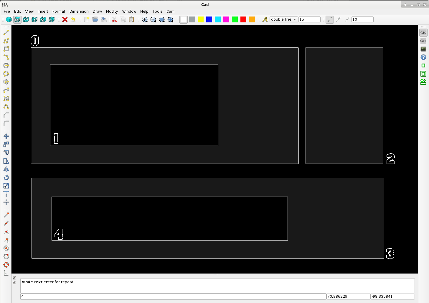
Here is some info what is happening after the algoritme has recognized the objects for inside each other, or not..
This output list, is the base how to go further in the process.. By list manipulation you can make a sequence for cutting.
There is beside that info almost unlimited to acces to info about product contour dimension, shape, area, etc.. that can be used by the process. We got about 75 parameters for each drawed item, divided up into 15 integers and 60 double value's. This includes everything up to dxf, stl, contournumbers, cw or ccw parameters, predifined intersection points, etc. So much info. More then a draftsight drawing.
I was thinking of how your program should calculate the process.
stand alone contour added *it : 2
master : 0 slave : 1
master : 0 slave : 1
master : 0 slave : 1
master : 0 slave : 1
master : 3 slave : 4
master : 3 slave : 4
master : 3 slave : 4
master : 3 slave : 4
Attachments:
Please Log in or Create an account to join the conversation.
- Grotius
-
Topic Author
- Offline
- Platinum Member
-
Less
More
- Posts: 2419
- Thank you received: 2348
22 Nov 2019 03:25 #150878
by Grotius
Replied by Grotius on topic QT C++ code samples
Hi there,
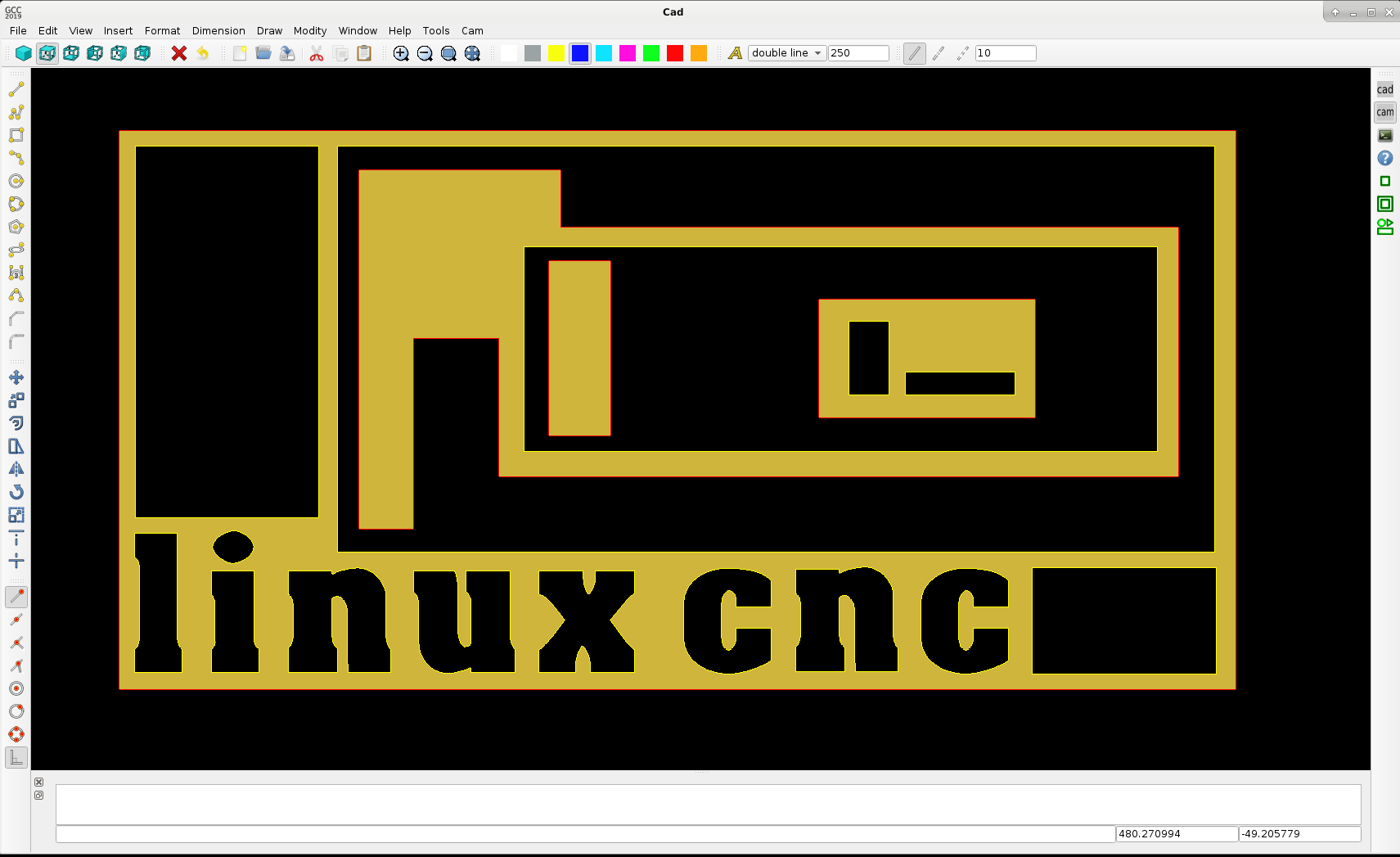
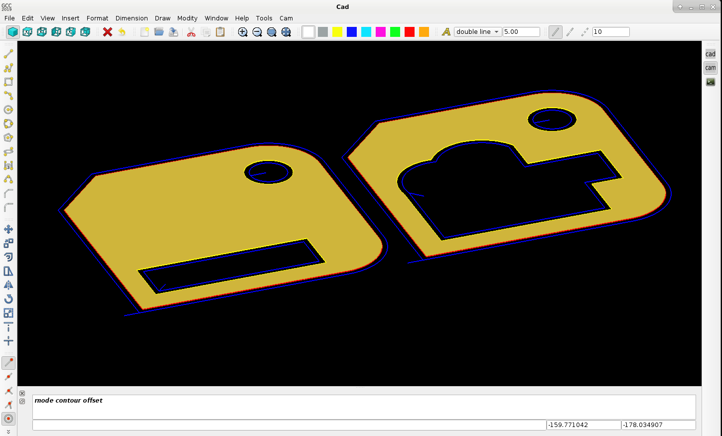
I had some difficult programming time the last day's. But we can now nest 3 parts deep.
This mean's part 1, may contain part 2, and part 2 may contain part 3. It's a very hard logic to write, it takes some up's and down's..
The nice thing is, the g-code logic is from most inner part to most outher part. And is keep part's together. So very good..
The red line is cw, outside cutting.
The yellow line is ccw, inside cutting.
Triangulation is done in the color old gold.
Next step is to implement the contour offset. This will become a tiny blue line around the contours. It will look fantastic...
Example plate 2000x1000mm with some text and parts nested 3 parts deep :
Attachments:
The following user(s) said Thank You: phillc54, tommylight, Clive S
Please Log in or Create an account to join the conversation.
- Grotius
-
Topic Author
- Offline
- Platinum Member
-
Less
More
- Posts: 2419
- Thank you received: 2348
29 Nov 2019 07:46 #151477
by Grotius
Replied by Grotius on topic QT C++ code samples
Hi linux friends,
A little project update for today.
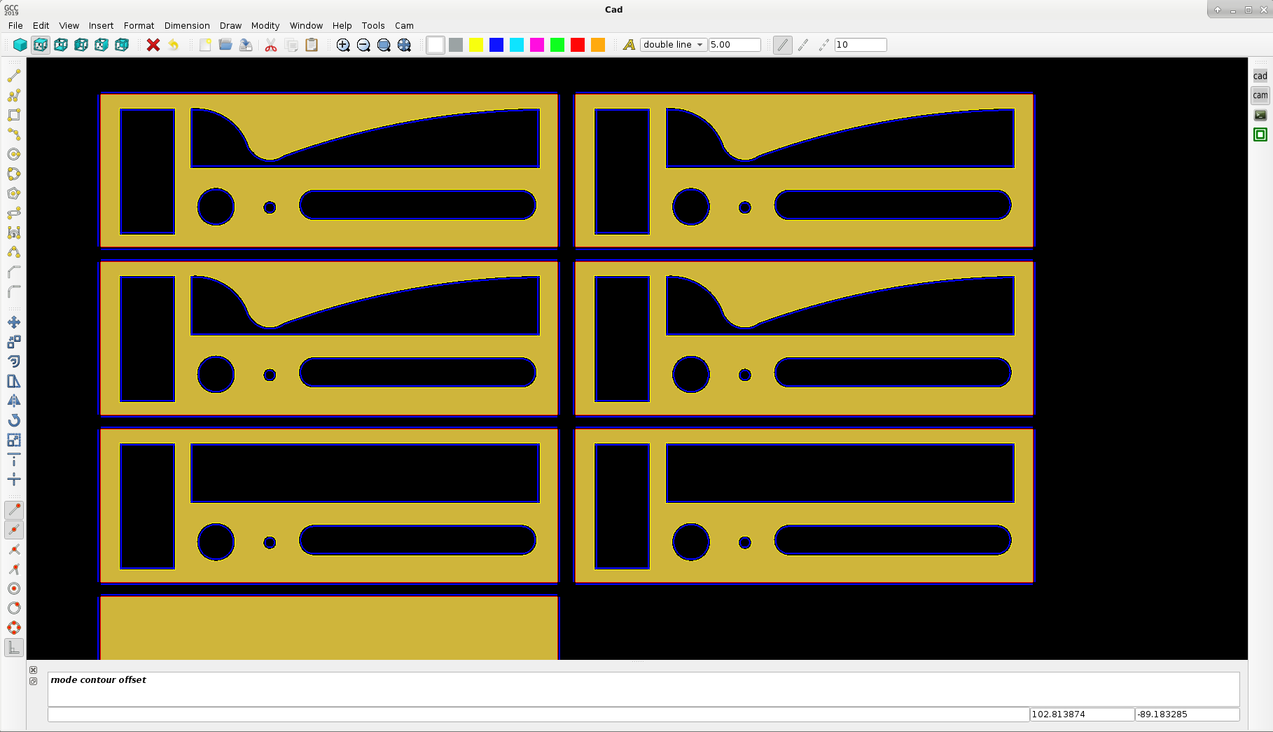
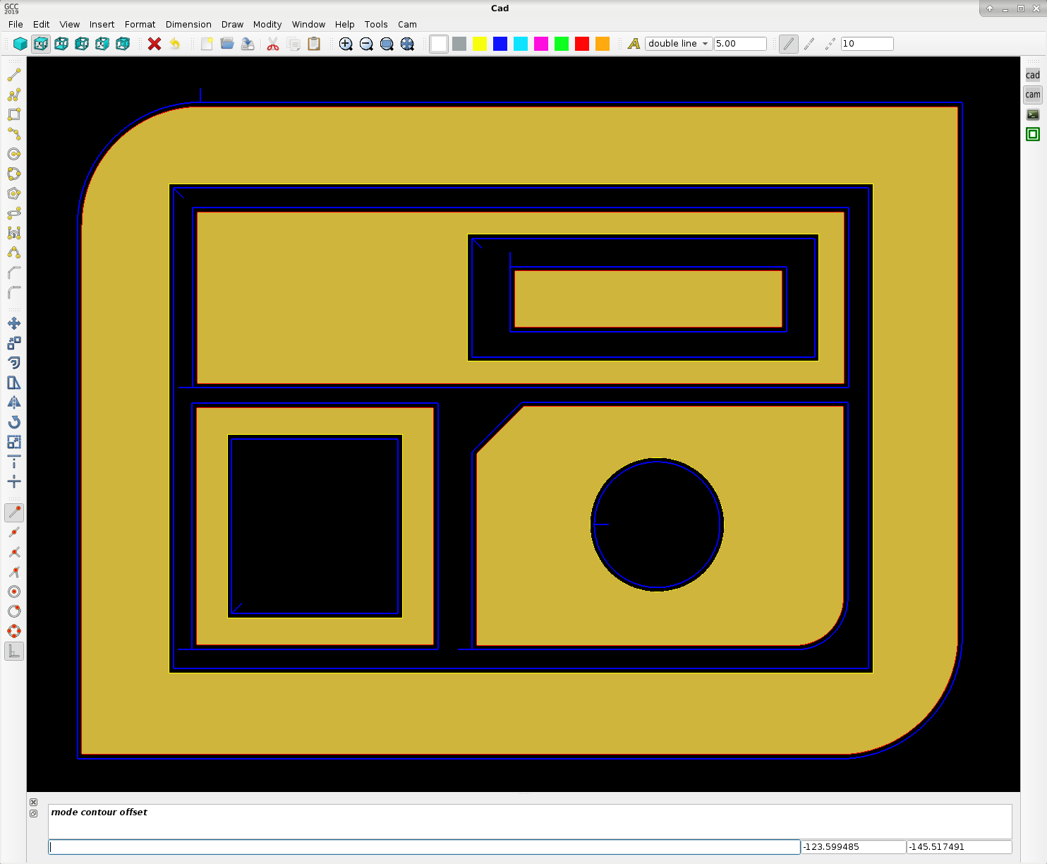
The contour offset class is in progess. Todo is to calculate the new offset intersection point's. line-line, line-arc etc..
The triangulation is a quite a difficult class to get as espected. But we are quite far in coding that class at the moment.
The tiny blue line is the generated tool offset path, chosen a tool diameter of 1.5mm
Red is clockwise contour, Yellow is counter clockwise contour. When the intersection's are done, we make the lead-in and lead out-logic.
So far so good. Have a nice day !
A little project update for today.
The contour offset class is in progess. Todo is to calculate the new offset intersection point's. line-line, line-arc etc..
The triangulation is a quite a difficult class to get as espected. But we are quite far in coding that class at the moment.
The tiny blue line is the generated tool offset path, chosen a tool diameter of 1.5mm
Red is clockwise contour, Yellow is counter clockwise contour. When the intersection's are done, we make the lead-in and lead out-logic.
So far so good. Have a nice day !
Attachments:
The following user(s) said Thank You: phillc54, tommylight, Clive S
Please Log in or Create an account to join the conversation.
- Grotius
-
Topic Author
- Offline
- Platinum Member
-
Less
More
- Posts: 2419
- Thank you received: 2348
29 Nov 2019 18:51 - 29 Nov 2019 21:15 #151516
by Grotius
Replied by Grotius on topic QT C++ code samples
Hi,
A short program update of today.
The contour intersection point's of the blue lines are calculated. It seems to work quite nice.
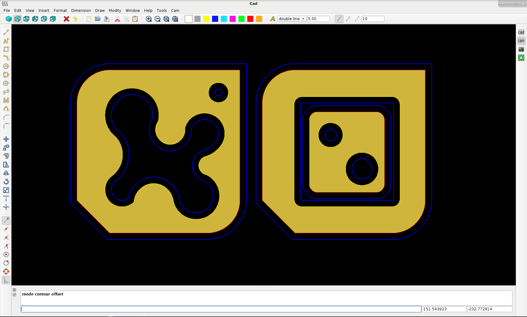
This cam calculation of 32 pieces of 100x100 products takes 1,39717 seconds to generate :
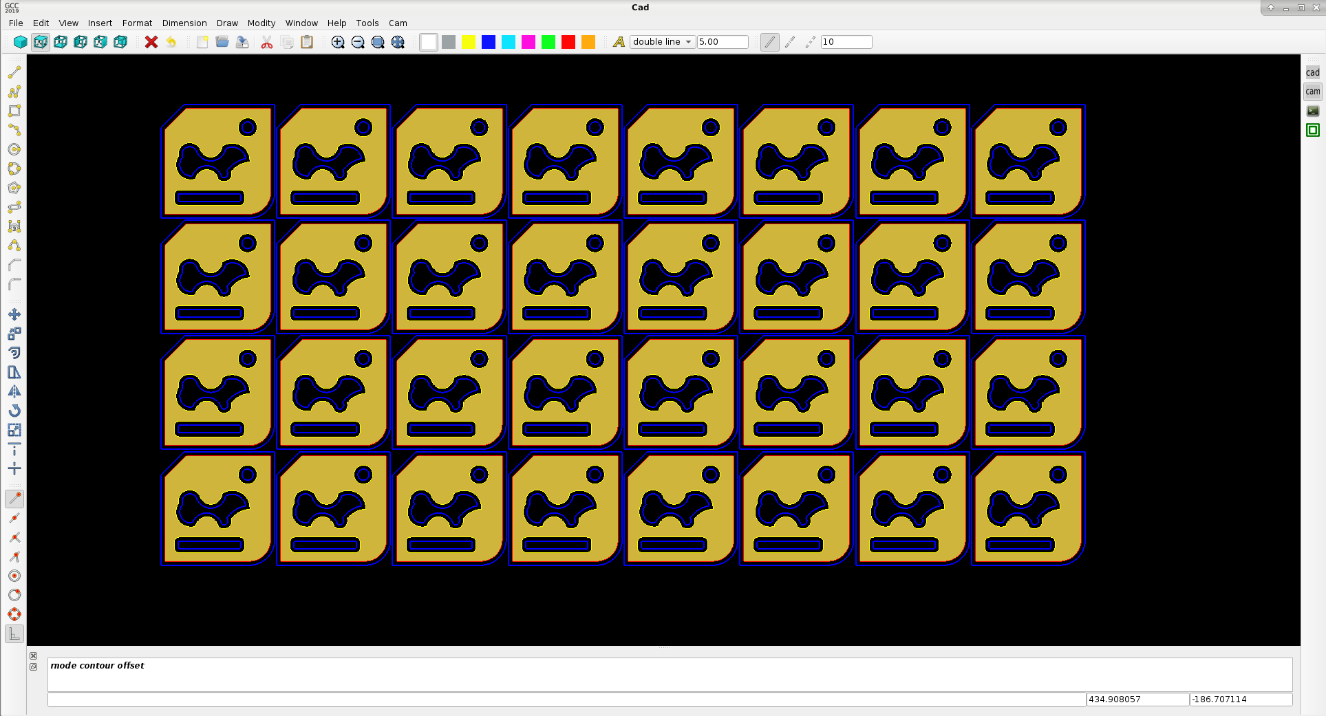
above 32 pieces have 1410 items like line's, arc's and circles.
Okey let's see if we can add lead-in and lead out to the products. Have a nice day !
Update : Auto generated lead in :
A short program update of today.
The contour intersection point's of the blue lines are calculated. It seems to work quite nice.
This cam calculation of 32 pieces of 100x100 products takes 1,39717 seconds to generate :
above 32 pieces have 1410 items like line's, arc's and circles.
Okey let's see if we can add lead-in and lead out to the products. Have a nice day !
Update : Auto generated lead in :
Attachments:
Last edit: 29 Nov 2019 21:15 by Grotius.
The following user(s) said Thank You: phillc54, tommylight, Clive S
Please Log in or Create an account to join the conversation.
- Grotius
-
Topic Author
- Offline
- Platinum Member
-
Less
More
- Posts: 2419
- Thank you received: 2348
30 Nov 2019 15:54 - 30 Nov 2019 18:07 #151580
by Grotius
Replied by Grotius on topic QT C++ code samples
Hi,
Today we added the G-code class to the program and did a Linuxcnc test. Users only have to press the cam button to see the
output like this. Below the g-code output in a spoiler.
The lead-in is implemented as a kind of macro behind the screen. This makes it able to use a dxf lead in template for users.
Lead in may be a 3d curve for example. The curve only needs a begin point and endpoint, see it as a vector..
Everything looks good. Have to make a link to the cut sequence (keep parts together), no problem.
I want to ask the linux users to comment about the following items :
- who wants to use code snippets? for example : little holes below .. mm slower .. % or for example a lead in path dxf macro?
- g_code parameters like : pierce Z speed, lead in speed (this is maybe a new item), etc. etc.
- special features.. ??
- PlasmaC features or postprocessor features ??
Attached the test g-code output :
Okey we are at a exiting moment with the program now, have a nice day and don't forget to comment about program features.
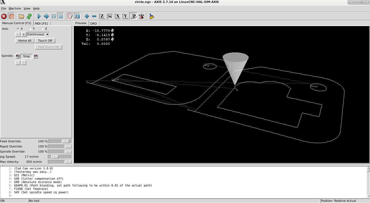
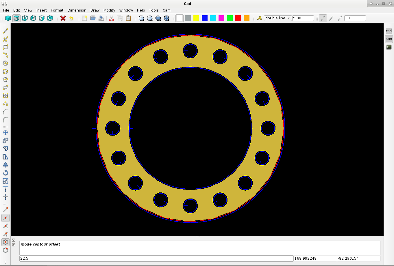
Another test today :
Showing a example of a pipe flange. Here we show how the triangulation is done to get a solid product with opengl.

With triangulation as a solid view :
Linuxcnc output :
Gcode of pipe flange in spoiler :
Okey i see we can optimize the holes to do a shortest path with keep parts together..
The lead in is nice.. it point's always to the center of the circle.. even when it's a g2.
Today we added the G-code class to the program and did a Linuxcnc test. Users only have to press the cam button to see the
output like this. Below the g-code output in a spoiler.
The lead-in is implemented as a kind of macro behind the screen. This makes it able to use a dxf lead in template for users.
Lead in may be a 3d curve for example. The curve only needs a begin point and endpoint, see it as a vector..
Everything looks good. Have to make a link to the cut sequence (keep parts together), no problem.
I want to ask the linux users to comment about the following items :
- who wants to use code snippets? for example : little holes below .. mm slower .. % or for example a lead in path dxf macro?
- g_code parameters like : pierce Z speed, lead in speed (this is maybe a new item), etc. etc.
- special features.. ??
- PlasmaC features or postprocessor features ??
Attached the test g-code output :
Warning: Spoiler!
(Cad Cam version 1.0.0)
(Yesterday was easy..)
G21 (Metric)
G40 (Cutter compensation off)
G90 (Absolute distance mode)
G64P0.01 (Path blending, set path following to be within 0.01 of the actual path)
F1500 (Set feedrate)
S45 (Set spindle speed cq power)
(Move to travelheight)
G0 Z 2.000
(Contour id : 1 )
G0 X -317.158 Y -123.101 Z 2.000
G0 Z 1.000
M3 S 45.000
G1 Z 0.000 F 500.000
G1 X -323.158 Y -123.101 Z 0.000 F 1000.000
G3 I 7.034 J 0.000 F 1400.000 (Circle)
M5
G0 Z 2.000
(Contour id : 2 )
G0 X -206.150 Y -123.101 Z 2.000
G0 Z 1.000
M3 S 45.000
G1 Z 0.000 F 500.000
G1 X -212.150 Y -123.101 Z 0.000 F 1000.000
G3 I 7.034 J 0.000 F 1400.000 (Circle)
M5
G0 Z 2.000
(Contour id : 3 )
G0 X -404.124 Y -205.101 Z 2.000
G0 Z 1.000
M3 S 45.000
G1 Z 0.000 F 500.000
G1 X -398.124 Y -205.101 Z 0.000 F 1000.000
G1 X -398.124 Y -122.272 Z 0.000 F 1400.000
G1 X -376.952 Y -101.101 Z 0.000 F 1400.000
G1 X -316.124 Y -101.101 Z 0.000 F 1400.000
G2 X -294.124 Y -123.101 Z 0.000 I 0.000 J -22.000 F 1400.000
G1 X -294.124 Y -183.101 Z 0.000 F 1400.000
G2 X -316.124 Y -205.101 Z 0.000 I -22.000 J -0.000 F 1400.000
G1 X -398.124 Y -205.101 Z 0.000 F 1400.000
M5
G0 Z 2.000
(Contour id : 4 )
G0 X -293.116 Y -205.101 Z 2.000
G0 Z 1.000
M3 S 45.000
G1 Z 0.000 F 500.000
G1 X -287.116 Y -205.101 Z 0.000 F 1000.000
G1 X -287.116 Y -122.272 Z 0.000 F 1400.000
G1 X -265.945 Y -101.101 Z 0.000 F 1400.000
G1 X -205.116 Y -101.101 Z 0.000 F 1400.000
G2 X -183.116 Y -123.101 Z 0.000 I 0.000 J -22.000 F 1400.000
G1 X -183.116 Y -183.101 Z 0.000 F 1400.000
G2 X -205.116 Y -205.101 Z 0.000 I -22.000 J -0.000 F 1400.000
G1 X -287.116 Y -205.101 Z 0.000 F 1400.000
M5
G0 Z 2.000
(Contour id : 5 )
G0 X -381.354 Y -188.098 Z 2.000
G0 Z 1.000
M3 S 45.000
G1 Z 0.000 F 500.000
G1 X -385.597 Y -192.341 Z 0.000 F 1000.000
G1 X -322.853 Y -192.341 Z 0.000 F 1400.000
G1 X -322.853 Y -176.573 Z 0.000 F 1400.000
G1 X -385.597 Y -176.573 Z 0.000 F 1400.000
G1 X -385.597 Y -192.341 Z 0.000 F 1400.000
M5
G0 Z 2.000
(Contour id : 6 )
G0 X -269.494 Y -160.237 Z 2.000
G0 Z 1.000
M3 S 45.000
G1 Z 0.000 F 500.000
G1 X -273.736 Y -155.994 Z 0.000 F 1000.000
G1 X -273.736 Y -192.108 Z 0.000 F 1400.000
G1 X -210.992 Y -192.108 Z 0.000 F 1400.000
G1 X -210.992 Y -171.643 Z 0.000 F 1400.000
G1 X -198.667 Y -171.643 Z 0.000 F 1400.000
G1 X -198.667 Y -152.852 Z 0.000 F 1400.000
G1 X -227.271 Y -152.852 Z 0.000 F 1400.000
G1 X -227.271 Y -136.560 Z 0.000 F 1400.000
G3 X -256.111 Y -137.656 Z 0.000 I -14.080 J -9.469 F 1400.000
G3 X -273.736 Y -155.994 Z 0.000 I -2.637 J -15.105 F 1400.000 (Arc)
M5
G0 Z 2.000
M30
Okey we are at a exiting moment with the program now, have a nice day and don't forget to comment about program features.
Another test today :
Showing a example of a pipe flange. Here we show how the triangulation is done to get a solid product with opengl.
With triangulation as a solid view :
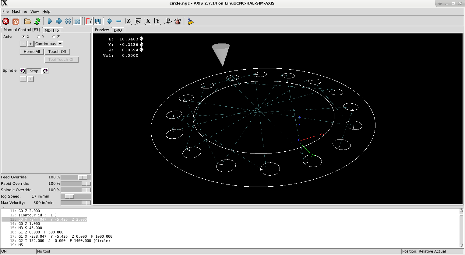
Linuxcnc output :
Gcode of pipe flange in spoiler :
Warning: Spoiler!
(Cad Cam version 1.0.0)
(Yesterday was easy..)
G21 (Metric)
G40 (Cutter compensation off)
G90 (Absolute distance mode)
G64P0.01 (Path blending, set path following to be within 0.01 of the actual path)
F1500 (Set feedrate)
S45 (Set spindle speed cq power)
(Move to travelheight)
G0 Z 2.000
(Contour id : 1 )
G0 X -244.047 Y -5.426 Z 2.000
G0 Z 1.000
M3 S 45.000
G1 Z 0.000 F 500.000
G1 X -238.047 Y -5.426 Z 0.000 F 1000.000
G2 I 152.000 J 0.000 F 1400.000 (Circle)
M5
G0 Z 2.000
(Contour id : 2 )
G0 X -178.047 Y -5.426 Z 2.000
G0 Z 1.000
M3 S 45.000
G1 Z 0.000 F 500.000
G1 X -184.047 Y -5.426 Z 0.000 F 1000.000
G3 I 98.000 J 0.000 F 1400.000 (Circle)
M5
G0 Z 2.000
(Contour id : 3 )
G0 X -90.547 Y 119.574 Z 2.000
G0 Z 1.000
M3 S 45.000
G1 Z 0.000 F 500.000
G1 X -96.547 Y 119.574 Z 0.000 F 1000.000
G3 I 10.500 J 0.000 F 1400.000 (Circle)
M5
G0 Z 2.000
(Contour id : 4 )
G0 X -90.547 Y -130.426 Z 2.000
G0 Z 1.000
M3 S 45.000
G1 Z 0.000 F 500.000
G1 X -96.547 Y -130.426 Z 0.000 F 1000.000
G3 I 10.500 J 0.000 F 1400.000 (Circle)
M5
G0 Z 2.000
(Contour id : 5 )
G0 X -211.047 Y -9.926 Z 2.000
G0 Z 1.000
M3 S 45.000
G1 Z 0.000 F 500.000
G1 X -211.047 Y -15.926 Z 0.000 F 1000.000
G3 I 0.000 J 10.500 F 1400.000 (Circle)
M5
G0 Z 2.000
(Contour id : 6 )
G0 X 38.953 Y -9.926 Z 2.000
G0 Z 1.000
M3 S 45.000
G1 Z 0.000 F 500.000
G1 X 38.953 Y -15.926 Z 0.000 F 1000.000
G3 I 0.000 J 10.500 F 1400.000 (Circle)
M5
G0 Z 2.000
(Contour id : 7 )
G0 X -177.617 Y 79.780 Z 2.000
G0 Z 1.000
M3 S 45.000
G1 Z 0.000 F 500.000
G1 X -181.859 Y 75.537 Z 0.000 F 1000.000
G3 I 7.425 J 7.425 F 1400.000 (Circle)
M5
G0 Z 2.000
(Contour id : 8 )
G0 X -0.840 Y -96.997 Z 2.000
G0 Z 1.000
M3 S 45.000
G1 Z 0.000 F 500.000
G1 X -5.083 Y -101.239 Z 0.000 F 1000.000
G3 I 7.425 J 7.425 F 1400.000 (Circle)
M5
G0 Z 2.000
(Contour id : 9 )
G0 X -171.253 Y -96.997 Z 2.000
G0 Z 1.000
M3 S 45.000
G1 Z 0.000 F 500.000
G1 X -167.010 Y -101.239 Z 0.000 F 1000.000
G3 I -7.425 J 7.425 F 1400.000 (Circle)
M5
G0 Z 2.000
(Contour id : 10 )
G0 X 5.524 Y 79.780 Z 2.000
G0 Z 1.000
M3 S 45.000
G1 Z 0.000 F 500.000
G1 X 9.766 Y 75.537 Z 0.000 F 1000.000
G3 I -7.425 J 7.425 F 1400.000 (Circle)
M5
G0 Z 2.000
(Contour id : 11 )
G0 X -138.039 Y 108.337 Z 2.000
G0 Z 1.000
M3 S 45.000
G1 Z 0.000 F 500.000
G1 X -143.583 Y 106.040 Z 0.000 F 1000.000
G3 I 9.701 J 4.018 F 1400.000 (Circle)
M5
G0 Z 2.000
(Contour id : 12 )
G0 X -42.369 Y -122.633 Z 2.000
G0 Z 1.000
M3 S 45.000
G1 Z 0.000 F 500.000
G1 X -47.912 Y -124.929 Z 0.000 F 1000.000
G3 I 9.701 J 4.018 F 1400.000 (Circle)
M5
G0 Z 2.000
(Contour id : 13 )
G0 X -199.809 Y -57.419 Z 2.000
G0 Z 1.000
M3 S 45.000
G1 Z 0.000 F 500.000
G1 X -197.513 Y -62.963 Z 0.000 F 1000.000
G3 I -4.018 J 9.701 F 1400.000 (Circle)
M5
G0 Z 2.000
(Contour id : 14 )
G0 X -203.254 Y 38.252 Z 2.000
G0 Z 1.000
M3 S 45.000
G1 Z 0.000 F 500.000
G1 X -205.550 Y 32.708 Z 0.000 F 1000.000
G3 I 4.018 J 9.701 F 1400.000 (Circle)
M5
G0 Z 2.000
(Contour id : 15 )
G0 X 27.716 Y -57.419 Z 2.000
G0 Z 1.000
M3 S 45.000
G1 Z 0.000 F 500.000
G1 X 25.420 Y -62.963 Z 0.000 F 1000.000
G3 I 4.018 J 9.701 F 1400.000 (Circle)
M5
G0 Z 2.000
(Contour id : 16 )
G0 X -129.724 Y -122.633 Z 2.000
G0 Z 1.000
M3 S 45.000
G1 Z 0.000 F 500.000
G1 X -124.181 Y -124.929 Z 0.000 F 1000.000
G3 I -9.701 J 4.018 F 1400.000 (Circle)
M5
G0 Z 2.000
(Contour id : 17 )
G0 X -34.054 Y 108.337 Z 2.000
G0 Z 1.000
M3 S 45.000
G1 Z 0.000 F 500.000
G1 X -28.510 Y 106.040 Z 0.000 F 1000.000
G3 I -9.701 J 4.018 F 1400.000 (Circle)
M5
G0 Z 2.000
(Contour id : 18 )
G0 X 31.161 Y 38.252 Z 2.000
G0 Z 1.000
M3 S 45.000
G1 Z 0.000 F 500.000
G1 X 33.457 Y 32.708 Z 0.000 F 1000.000
G3 I -4.018 J 9.701 F 1400.000 (Circle)
M5
G0 Z 2.000
M30
Okey i see we can optimize the holes to do a shortest path with keep parts together..
The lead in is nice.. it point's always to the center of the circle.. even when it's a g2.
Attachments:
Last edit: 30 Nov 2019 18:07 by Grotius.
The following user(s) said Thank You: tommylight, Clive S
Please Log in or Create an account to join the conversation.
- phillc54
-

- Offline
- Platinum Member
-
Less
More
- Posts: 5711
- Thank you received: 2100
01 Dec 2019 00:17 #151621
by phillc54
Replied by phillc54 on topic QT C++ code samples
This just gets better and better, awesome job...
If users could create their own custom postprocessor, similar to say SheetCam would be good.
If users could create their own custom postprocessor, similar to say SheetCam would be good.
The following user(s) said Thank You: tommylight, Clive S, Grotius
Please Log in or Create an account to join the conversation.
- Grotius
-
Topic Author
- Offline
- Platinum Member
-
Less
More
- Posts: 2419
- Thank you received: 2348
02 Dec 2019 13:04 #151741
by Grotius
Replied by Grotius on topic QT C++ code samples
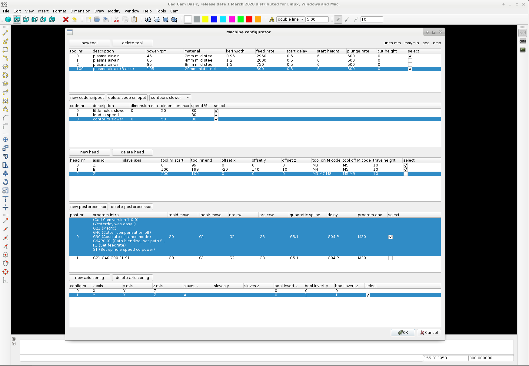
Hi Phill,
Thank you for your advice.
Attached a example of how the post processor can be set up. At least how i think it can be done at this moment.
It has several more items, like a tool library, code snippets and a axis configuration. This all can be loaded and saved in a configuration file related to the program. Editing the configuration file can also be done in Geanny or Wordpad.
I think this Treemodel structure can also be nice for editing the contour cut path's in the main cad cam screen.
- Soon try to add pocket milling operations.
Attachments:
The following user(s) said Thank You: phillc54, tommylight, Clive S
Please Log in or Create an account to join the conversation.
- Grotius
-
Topic Author
- Offline
- Platinum Member
-
Less
More
- Posts: 2419
- Thank you received: 2348
04 Dec 2019 14:00 #151994
by Grotius
Replied by Grotius on topic QT C++ code samples
Hi,
I programmed the tools in a seperate window. It's done in a tableview format. Just like excel. Tools can be saved and loaded trough the text file tools.txt.
The tooltable can add and delete lines, insert lines at a selected place, the lines can be moved up and down to sort your tool table.
I think this is quite good..
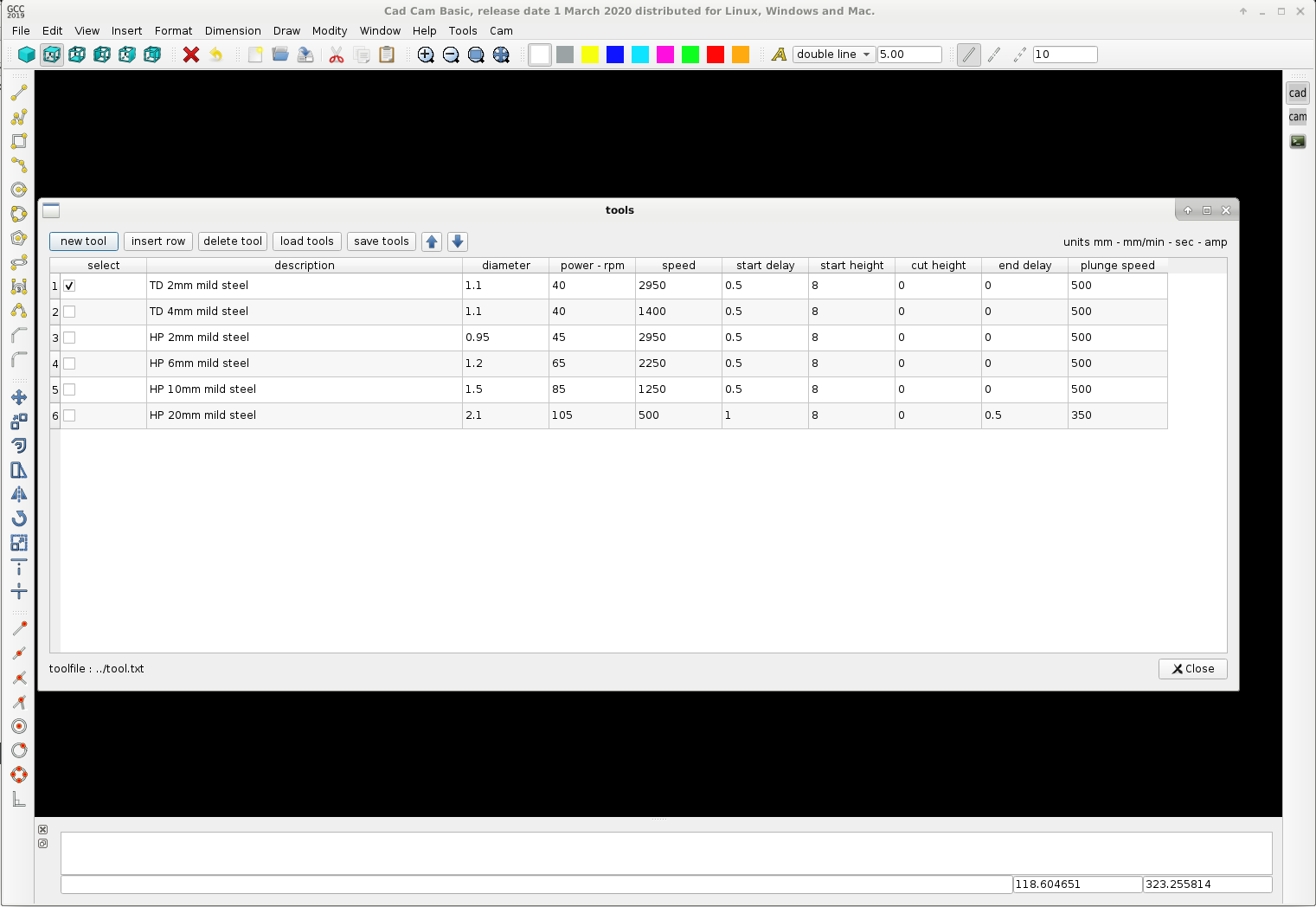
The text file can be edited off line. A tool.txt example output :
Okey this tool window template we can use as template for the postprocessor window and the machine head's window.
Problably the contour editing goes trough a tree structure..
Have a nice day !
I programmed the tools in a seperate window. It's done in a tableview format. Just like excel. Tools can be saved and loaded trough the text file tools.txt.
The tooltable can add and delete lines, insert lines at a selected place, the lines can be moved up and down to sort your tool table.
I think this is quite good..
The text file can be edited off line. A tool.txt example output :
Warning: Spoiler!
select
2
description
TD 2mm mild steel
diameter
1.1
power - rpm
40
cutspeed
2950
start delay
0.5
start height
8
cut height
0
end delay
0
plunge speed
500

select
0
description
TD 4mm mild steel
diameter
1.1
power - rpm
40
cutspeed
1400
start delay
0.5
start height
8
cut height
0
end delay
0
plunge speed
500

select
0
description
HP 2mm mild steel
diameter
0.95
power - rpm
45
cutspeed
2950
start delay
0.5
start height
8
cut height
0
end delay
0
plunge speed
500

select
0
description
HP 6mm mild steel
diameter
1.2
power - rpm
65
cutspeed
2250
start delay
0.5
start height
8
cut height
0
end delay
0
plunge speed
500

select
0
description
HP 10mm mild steel
diameter
1.5
power - rpm
85
cutspeed
1250
start delay
0.5
start height
8
cut height
0
end delay
0
plunge speed
500

select
0
description
HP 20mm mild steel
diameter
2.1
power - rpm
105
cutspeed
500
start delay
1
start height
8
cut height
0
end delay
0.5
plunge speed
350
Okey this tool window template we can use as template for the postprocessor window and the machine head's window.
Problably the contour editing goes trough a tree structure..
Have a nice day !
Attachments:
The following user(s) said Thank You: phillc54, tommylight
Please Log in or Create an account to join the conversation.
- Grotius
-
Topic Author
- Offline
- Platinum Member
-
Less
More
- Posts: 2419
- Thank you received: 2348
13 Dec 2019 21:28 #152613
by Grotius
Replied by Grotius on topic QT C++ code samples
Hi,
Bit by bit we go on. I had difficult times constructing a combobox with multiple data on the same line and qt has a tiny bug according
to display the toolbar order. So far no problems anymore.
At the moment doing some work on the cam window on the right of the screen. The treewidget is interacting with the contours.
The buttonboxes data in the toolbar are saved and loaded and refreshed during program execution.
I need some more time to make it as espected..
Have a nice day !
Attachments:
The following user(s) said Thank You: phillc54, tommylight, Clive S, emilvv
Please Log in or Create an account to join the conversation.
- Grotius
-
Topic Author
- Offline
- Platinum Member
-
Less
More
- Posts: 2419
- Thank you received: 2348
31 Dec 2019 15:21 - 31 Dec 2019 15:22 #153606
by Grotius
Replied by Grotius on topic QT C++ code samples
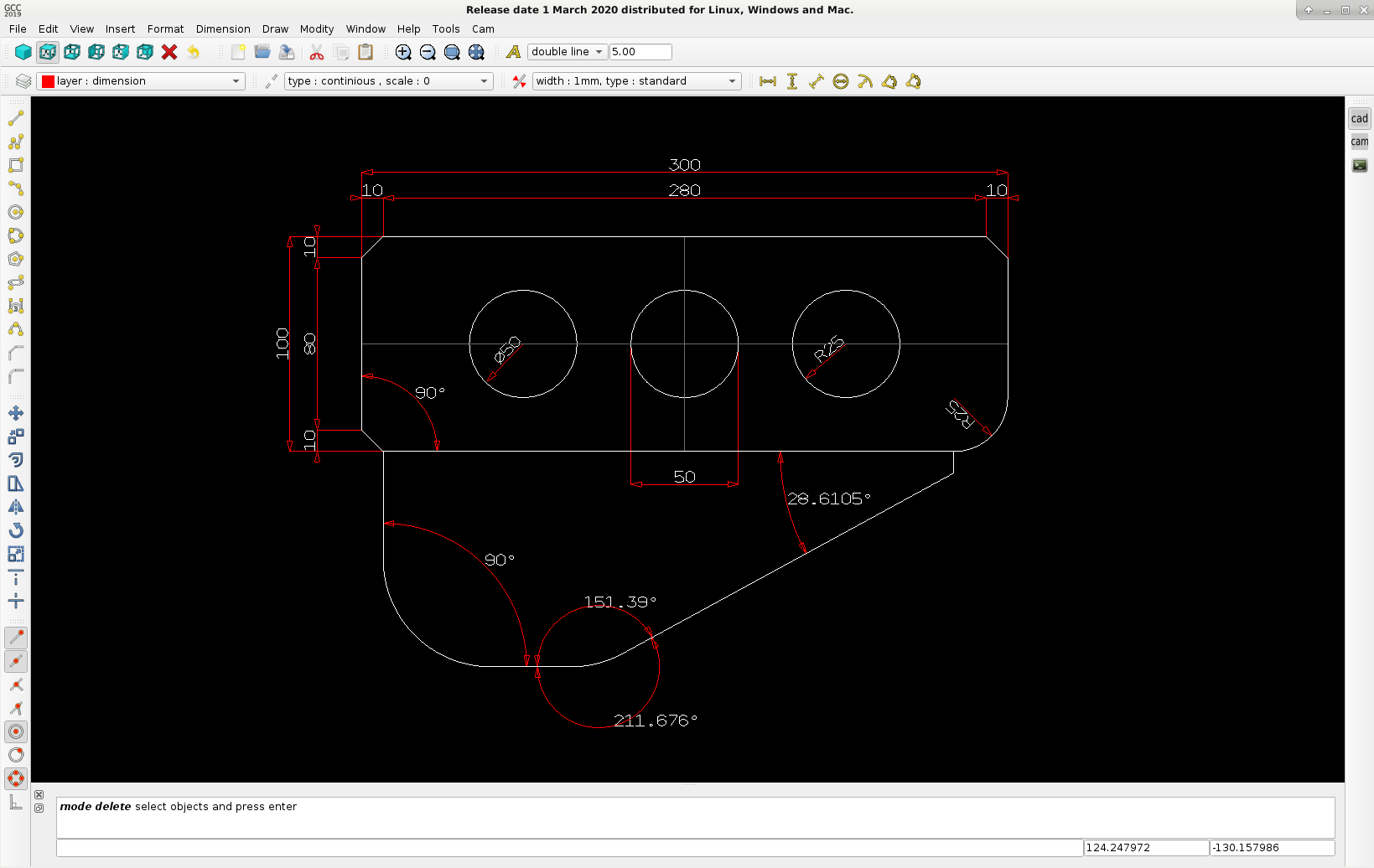
Hi guy's.
Everyone a good new year !
For the cad/cam program i spent some time in adding dimension features, see the example picture.
If users need a factory drawing, it needs dimension's and it must be printed to paper.. If not, it's useless..
I have read some document's about printing the opengl screen. We can save it as png or bitmap,
but that will result in a very bad output for the printer resolution.
So i am more thinking to output a pdf file (vector style) for printing... The pdf file does not need the opengl parameters. It only needs
the array data... I have to investegate more time about setting up a pdf file from scratch with c++.
So far so good, the dimension class works nice !
Attachments:
Last edit: 31 Dec 2019 15:22 by Grotius.
The following user(s) said Thank You: phillc54, tommylight, Clive S
Please Log in or Create an account to join the conversation.
Time to create page: 0.903 seconds