QT C++ code samples
- Grotius
-
 Topic Author
- Offline
- Platinum Member
-

Less
More
- Posts: 2419
- Thank you received: 2344
15 Oct 2019 19:15 #147942
by Grotius
Replied by Grotius on topic QT C++ code samples
Hi,
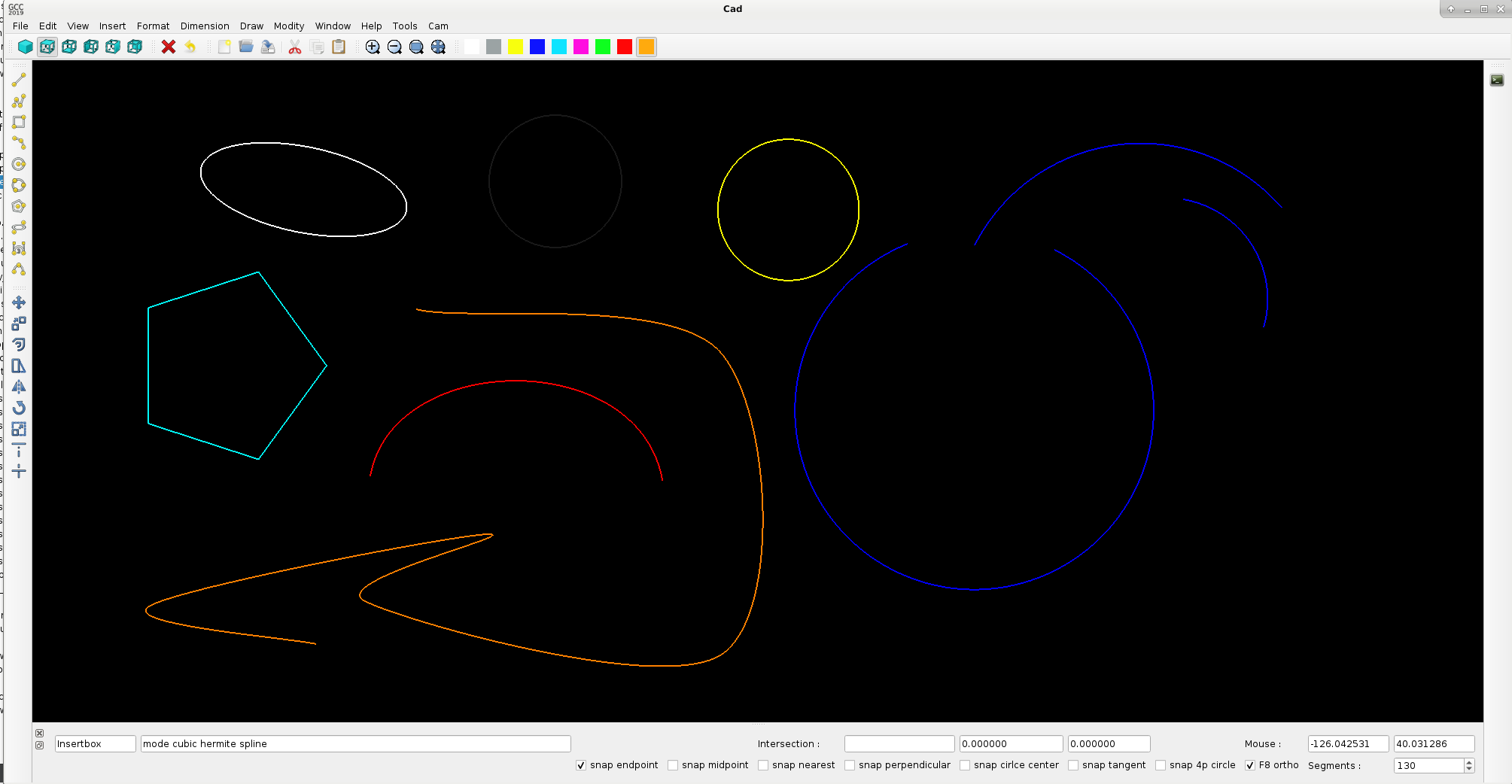
A little project update..
Integrated to the cad side :
- draw ellipse. => color white
- draw cubic bezier curve. => color red
- draw a cubic hermite spline. => color orange.
integrated snap functions : endpoint, midpoint, nearest, perpendicular, tangent, ortho.
Todo : chamfer and fillet functions..
A little project update..
Integrated to the cad side :
- draw ellipse. => color white
- draw cubic bezier curve. => color red
- draw a cubic hermite spline. => color orange.
integrated snap functions : endpoint, midpoint, nearest, perpendicular, tangent, ortho.
Todo : chamfer and fillet functions..
Attachments:
The following user(s) said Thank You: phillc54, chimeno, tommylight, Clive S, emilvv
Please Log in or Create an account to join the conversation.
- Grotius
-
 Topic Author
- Offline
- Platinum Member
-

Less
More
- Posts: 2419
- Thank you received: 2344
18 Oct 2019 21:06 #148224
by Grotius
Replied by Grotius on topic QT C++ code samples
Hi,
Thank you all for the thank you's.
The chamfer and fillet algoritmes are ready and tested. It works nice..
Later on i have to expand the chamfer and fillet function for a fillet between a arc with a line.. I will put this on the list.
For now it's ready for line -> line chamfer and fillet. Oke i am satisfied so far.
At the moment implementing more and more keyboard automation.
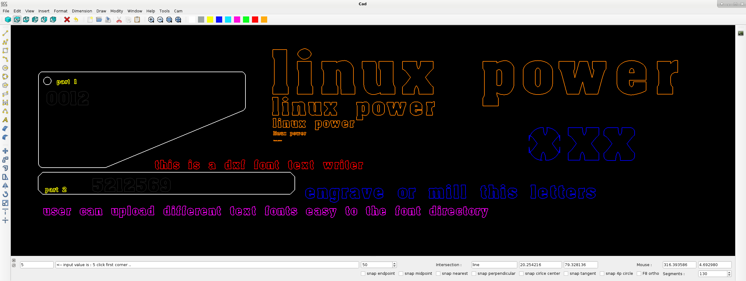
Will test to implement a letter fonds in the program based on a dxf drawing for each letter. In this way each font can have
a font directory with the dxf letters from a to z and from 0 to 9.
In this way the text can be inserted by typing the keyboard, and can be used directly with the cnc.
Using the OpenGL way for letter fonts, can be frustrating and useless for cnc.
So far so good..
Attachments:
The following user(s) said Thank You: phillc54, tommylight
Please Log in or Create an account to join the conversation.
- rodw
-

- Offline
- Platinum Member
-

Less
More
- Posts: 11525
- Thank you received: 3860
19 Oct 2019 07:21 #148294
by rodw
Replied by rodw on topic QT C++ code samples
Maybe you could convert fonts to dxf with this.
www.thingiverse.com/thing:96714
Seems like its had a bit of input from Linuxcnc guys.
www.thingiverse.com/thing:96714
Seems like its had a bit of input from Linuxcnc guys.
Please Log in or Create an account to join the conversation.
- Grotius
-
 Topic Author
- Offline
- Platinum Member
-

Less
More
- Posts: 2419
- Thank you received: 2344
19 Oct 2019 21:37 #148367
by Grotius
Replied by Grotius on topic QT C++ code samples
Attachments:
The following user(s) said Thank You: phillc54, tommylight
Please Log in or Create an account to join the conversation.
- Grotius
-
 Topic Author
- Offline
- Platinum Member
-

Less
More
- Posts: 2419
- Thank you received: 2344
24 Oct 2019 01:04 #148664
by Grotius
Replied by Grotius on topic QT C++ code samples
Hi,
A little project update.
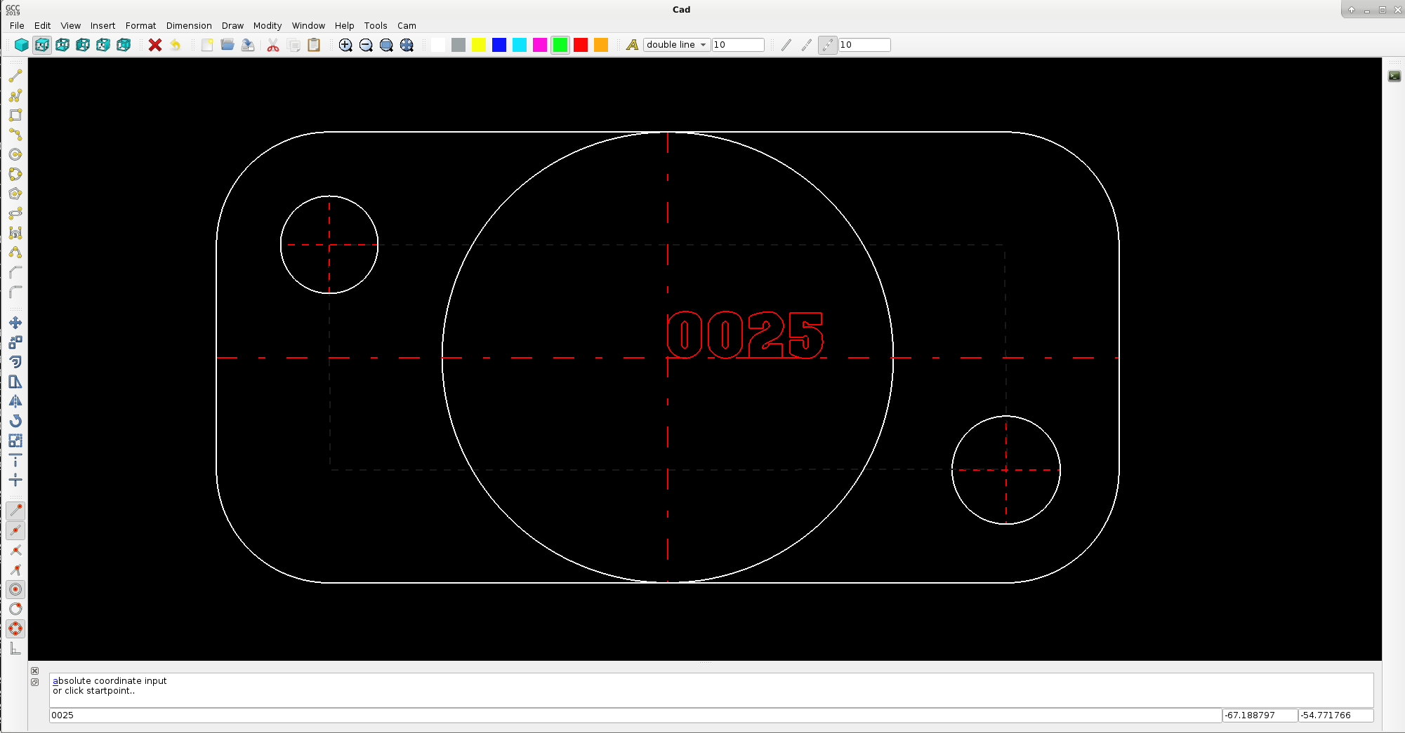
Integrated keyboard functions for creating a rectangular or line from absolute or relative keyboard coordinate inputs.
Added linetype's to the program. I hope to integrate the dimension class coming time.
Made a sample drawing. I am satisfied so far.
I hope to start the cam side soon !!
Ohh, i remember we need a printer function for printing the drawing on a deskjet..
Maybe add a A1 template also..
Attachments:
The following user(s) said Thank You: phillc54, tommylight, Clive S
Please Log in or Create an account to join the conversation.
- Grotius
-
 Topic Author
- Offline
- Platinum Member
-

Less
More
- Posts: 2419
- Thank you received: 2344
24 Oct 2019 08:34 - 24 Oct 2019 08:43 #148681
by Grotius
Replied by Grotius on topic QT C++ code samples
Last update for today.. I think it's quite nice info.
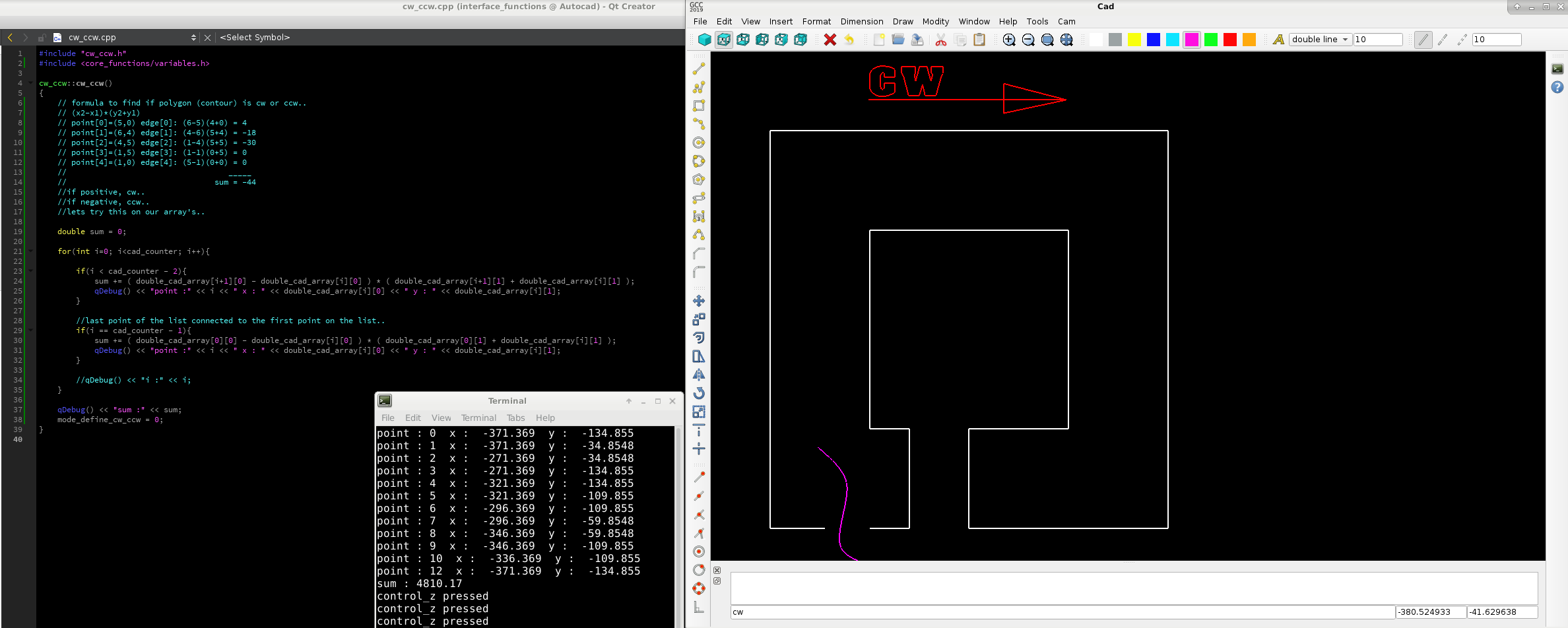
For the cam application i was thinking how to define if a contour is cw (clockwise) or ccw (counterclockwise) for a long time.
We need this to know if we want a correct automated contour offset.
But today i did several contour test's with a tiny formula, and it is satisfying the program needs so far.
In the past we made the cam offset logic at this page : forum.linuxcnc.org/41-guis/36768-qt-c-code-samples?start=70
I remember a conversation with John.
But at that time i was guessing on wich side the contour offset had to be done..
Attached a code example if contour is cw or ccw. Is the result (sum) positive, the contour is cw.
Is the result negative, the contour is ccw.
We can calculate wich line's are members of the outer contour.. This one get's a outside cw offset for plasma..
if the contour is a rearranged ccw, we flip it into a cw, and done..
One good thing to mention. It works also on open contours. So if a drawing is not correct, it will do the job. We can build in a closed contour fault margin, let's say lines that are not connected within 1 mm are accepted as closed contour.
Attachments:
Last edit: 24 Oct 2019 08:43 by Grotius.
The following user(s) said Thank You: tommylight, Clive S
Please Log in or Create an account to join the conversation.
- Grotius
-
 Topic Author
- Offline
- Platinum Member
-

Less
More
- Posts: 2419
- Thank you received: 2344
30 Oct 2019 01:12 - 30 Oct 2019 01:12 #149090
by Grotius
Replied by Grotius on topic QT C++ code samples
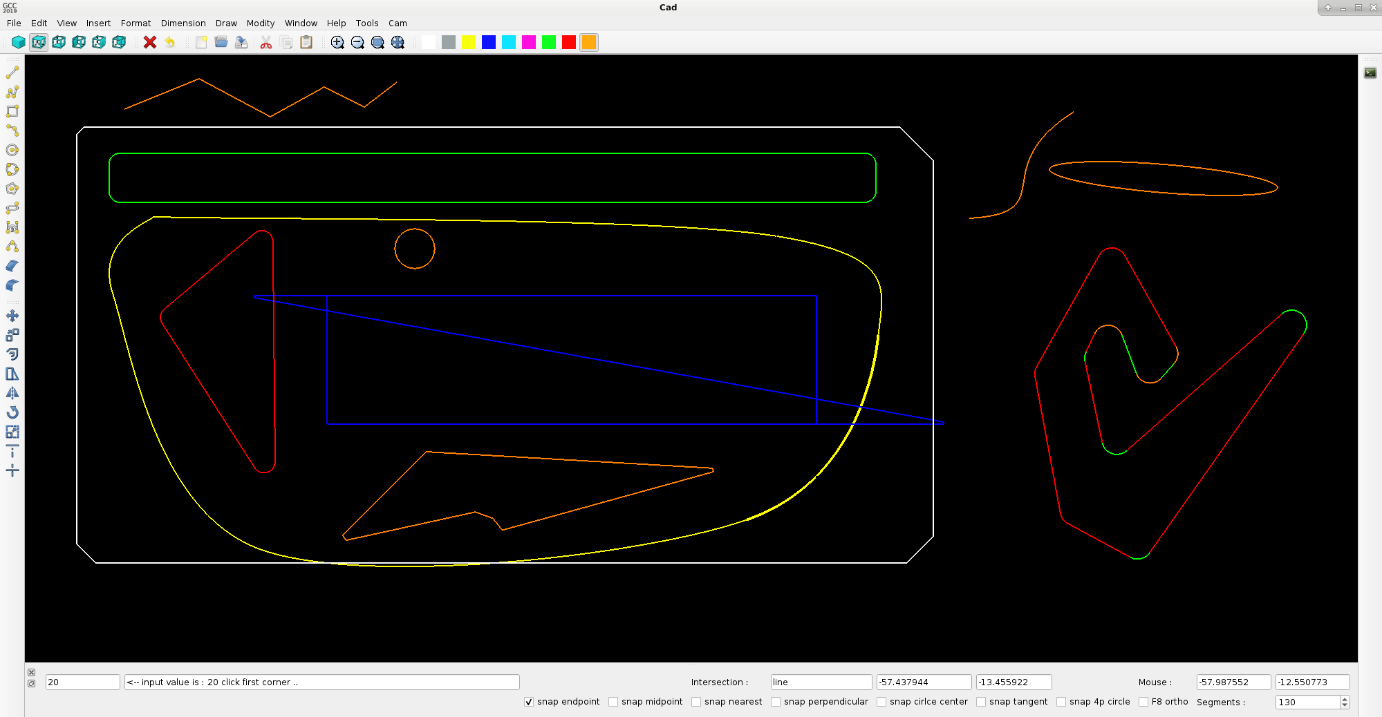
Little project update..
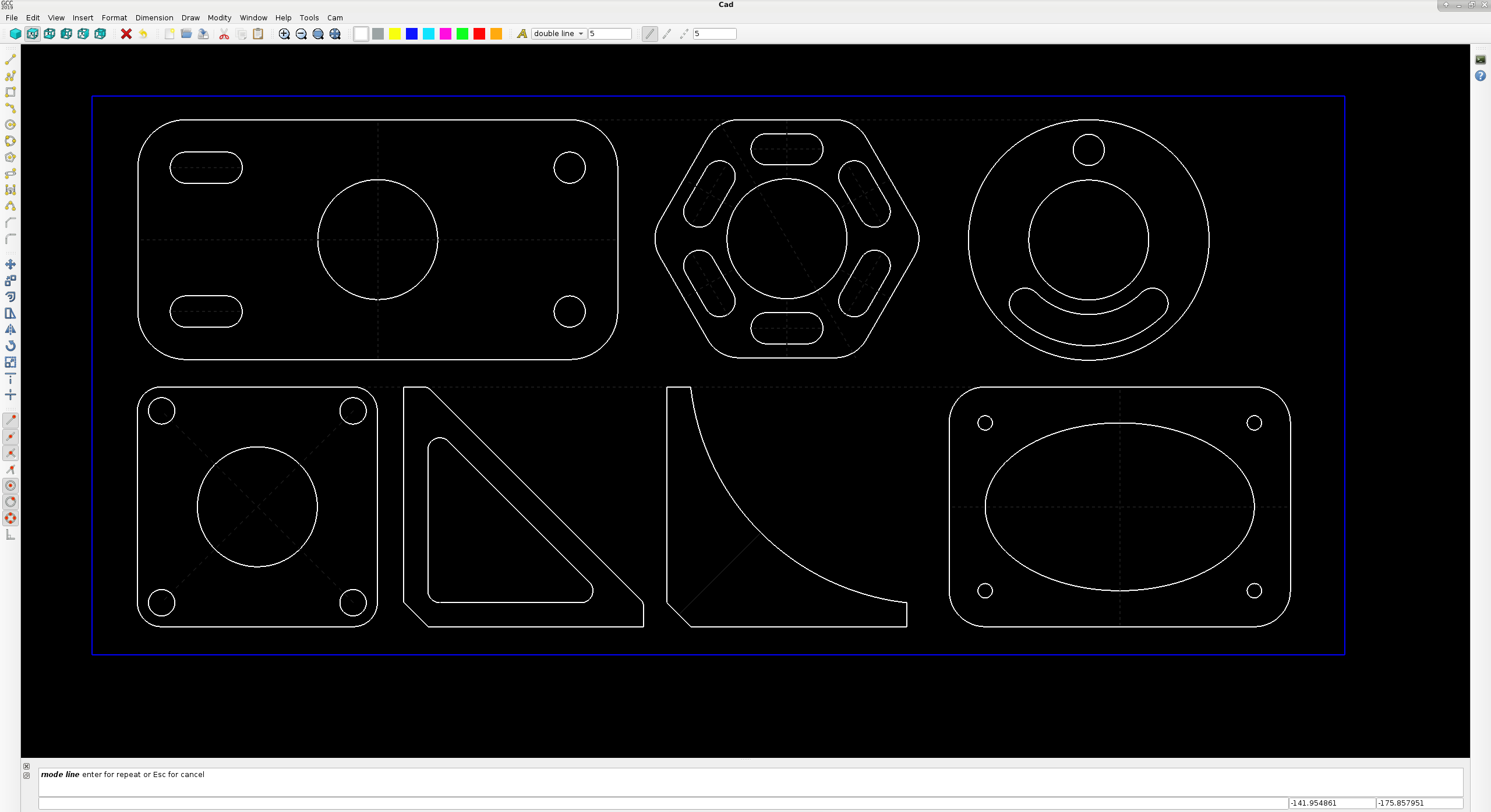
Made a sample drawing to find out the program functionality at the moment.
I have work on several tiny cases.
To make this drawing, multiple modify functions are used like :
- offset, rotate, copy, move, mirror, chamfer, fillet
The used draw functions :
- line, line_strip, 2p_circle, 6 side polygon, ellipse, arc
For now i am satisfied so far.
Hopely within a few day's we can start with the g_code processing part.. This will become fun for sure..
I wish everyone a good day !
Attachments:
Last edit: 30 Oct 2019 01:12 by Grotius.
The following user(s) said Thank You: phillc54, tommylight, Clive S, thefabricator03
Please Log in or Create an account to join the conversation.
- tommylight
-

- Away
- Moderator
-

Less
More
- Posts: 20980
- Thank you received: 7151
30 Oct 2019 07:34 #149130
by tommylight
Replied by tommylight on topic QT C++ code samples
Never mind us, we're just drooling here ! 
Please Log in or Create an account to join the conversation.
- Grotius
-
 Topic Author
- Offline
- Platinum Member
-

Less
More
- Posts: 2419
- Thank you received: 2344
30 Oct 2019 23:36 - 30 Oct 2019 23:39 #149239
by Grotius
Replied by Grotius on topic QT C++ code samples
@Thank you Tom..
I googled "drooling", i understand it now.
Today i solved most of the tiny cases..
Added today :
-add shift key for anti select an item.
-keyboard input distance for copy with ortho
-added a angle start and angle recalculate function after a arc mirror
-added midpoint for chamfer line
-added arc curve midpoint for fillet arc
-added arc fillet endpoints to curve.
Have to do left :
-expand the dxf write file and read file class for ellipse and bezier curve and spline.. This is not difficult to do
-add arc-arc trim, arc-line trim, arc-arc extend, arc-line extend
-add arc-line fillet, arc-arc fillet
-add select previous object
-add dimension class
-change the extend and trim icons into a more fancy icon
Thinking about :
1. Excel file output on top of a dxf file output.
This excel file output is usefull when a calculation program is linked with python. All drawing parameters are available.
2. Autonesting algoritme..
3. Fractal based patterns.. or something to do with fractals and random calculation. Also a time based or animation based
calculation is interesting to do. But it has to be usefull within the cad cam program.
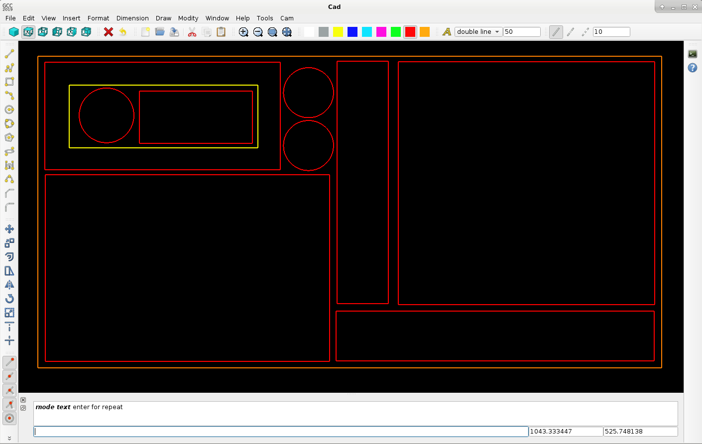
For autonesting the output must be something like this :
-orange = 1500x3000mm plate
-red = outside contour
-yellow = inside contour
How would you code this?
if else.. area 1 > area 2.. check longest object, etc.. Input about autonesting thought's is welcome !
Attachments:
Last edit: 30 Oct 2019 23:39 by Grotius.
The following user(s) said Thank You: tommylight, Clive S
Please Log in or Create an account to join the conversation.
- tommylight
-

- Away
- Moderator
-

Less
More
- Posts: 20980
- Thank you received: 7151
31 Oct 2019 00:00 #149241
by tommylight
Replied by tommylight on topic QT C++ code samples
At the moment i have no idea about autonesting, well i have no idea about anything, been working to much lately !
Regards,
Tom.
Regards,
Tom.
The following user(s) said Thank You: Grotius
Please Log in or Create an account to join the conversation.
Time to create page: 0.216 seconds

