servo dac offset
- bkt
-
 Topic Author
- Offline
- Platinum Member
-

- Posts: 1110
- Thank you received: 113
Please Log in or Create an account to join the conversation.
- PCW
-

- Online
- Moderator
-

- Posts: 17464
- Thank you received: 5101
If P is 0 this is the expected behaviour
(pncconf will not have faults because its tests are open loop so there _is_ no following error)
Please Log in or Create an account to join the conversation.
- bkt
-
 Topic Author
- Offline
- Platinum Member
-

- Posts: 1110
- Thank you received: 113
..... this is clear ...(pncconf will not have faults because its tests are open loop so there _is_ no following error)
ok ... but with P = 10, P=50, P=100, P=1000 is the same ....If P is 0 this is the expected behaviour
Please Log in or Create an account to join the conversation.
- PCW
-

- Online
- Moderator
-

- Posts: 17464
- Thank you received: 5101
including
PID output
PID command input
PID feedback input
PID enable
etc
Please Log in or Create an account to join the conversation.
- bkt
-
 Topic Author
- Offline
- Platinum Member
-

- Posts: 1110
- Thank you received: 113
The motor run at desired vel .... and move to desired position .... (with some error because ferror is set to hight number for test the system)
regards
giorgio
Please Log in or Create an account to join the conversation.
- bkt
-
 Topic Author
- Offline
- Platinum Member
-

- Posts: 1110
- Thank you received: 113
Please Log in or Create an account to join the conversation.
- andypugh
-

- Offline
- Moderator
-

- Posts: 19741
- Thank you received: 4579
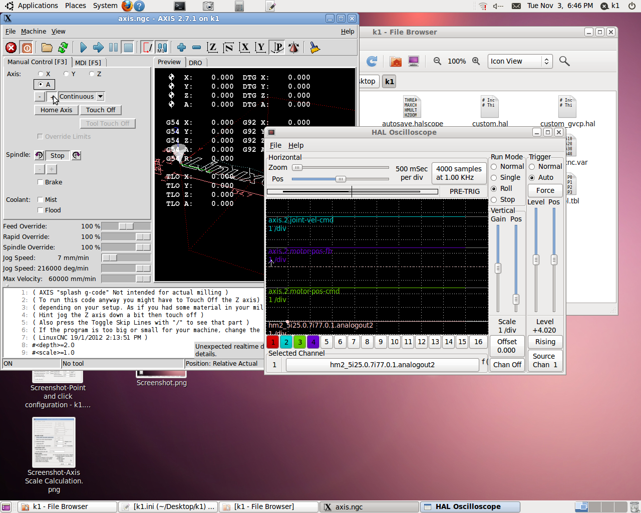
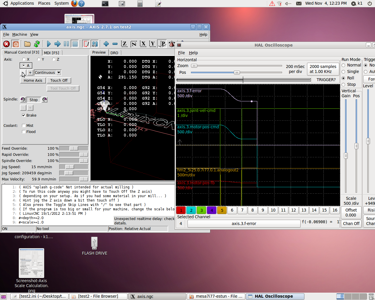
In roll-mode the data slides out from the trigger point to the left.
Please Log in or Create an account to join the conversation.
- bkt
-
 Topic Author
- Offline
- Platinum Member
-

- Posts: 1110
- Thank you received: 113
jog
the motor moves in the desired direction and at the desired speed
The motor stops when the desired position
automatically
engine " follows " the programmed path without much accuracy (they are testing and I set a high ferror )
It stops at the end of the program cycle in the wrong position , but very slowly back to the correct position when the program is now completed at least 1 minute
This default behavior qualceh good soul knows me indicate what is the symptom ? (is possible from motitor see anythings? these situation suggest to control somethings??)
My scale encoder and pid.... I set only P and I both drive on which LCNC , and a very low value ( 0.02 % ) of FF1 on LCNC and feedfoward percentage on the drive ......
I 250 ( * 4 ) pulses per revolution of LCNC and 2500 ( * 4 ) on the drive .... as I said the drive provides a function to reduce the pulses per revolution to control .... 1000rpm max speed reducer 10/1 ( 10 engine rpm = 1 turn led ) encoder ratio 27.7778 my units are degrees 1 tour conducted = 360 ° = 3600 ° engine
@PCW .... or other good soul man
reghards
giorgio
Please Log in or Create an account to join the conversation.
- PCW
-

- Online
- Moderator
-

- Posts: 17464
- Thank you received: 5101
PWM frequency is meaningless (not used by 7I77)
Most of your tuning is done with FF1 (assuming your drives are in velocity mode)
and then P is increased until it becomes unstable than backed off about 50%
FF1 = 1.0 if you set the analog output scale properly = machine units per second
(degrees per second at 10V for rotary axis) As the tutorial suggests, too much FF1
makes the position lead the command, while too little make the position lag the command
Unless you have extreme accuracy requirements (a coulple um),
A 1 KHz update rate is fine for velocity mode servos
(the drives themselves close the velocity loop at a much higher rate)
Please Log in or Create an account to join the conversation.
- bkt
-
 Topic Author
- Offline
- Platinum Member
-

- Posts: 1110
- Thank you received: 113
That is, when I select internal 5i25 config and 7i77x2 with one 7I77,
as soon as I press the accept changes button, a 7I77 I/O and a 7I77 PWM tab appear
the 7I77 I/O tab has the TB7 and TB8 I/O and the 7I77 PWM tab has the TB5 I/O:
...your response to other my post .... so I call analog output PWM .... in pncconfig when I choose In TB5 pwm signal fro "A axis" (for example) I not have other choice only pwm .... I have not investigated the possibility of setting PWM output differently on TB5 as I see no other choices on PNCCONFIG on ubuntu 10.04 .... show me how to select your own screen on an analog output PNCCONFIG properly .... I would like to pncconfig understand if my version has broken something else .... I felt that installed with English worked well ....
The better chice is control .hal file ....
Please Log in or Create an account to join the conversation.


