Search Results (Searched for: 7i76e)
- rodw

01 Jun 2026 02:30
- tommylight

01 Jun 2026 01:28
Replied by tommylight on topic Ethernet connection to Mesa 7i76e disconnecting on its own after one minute
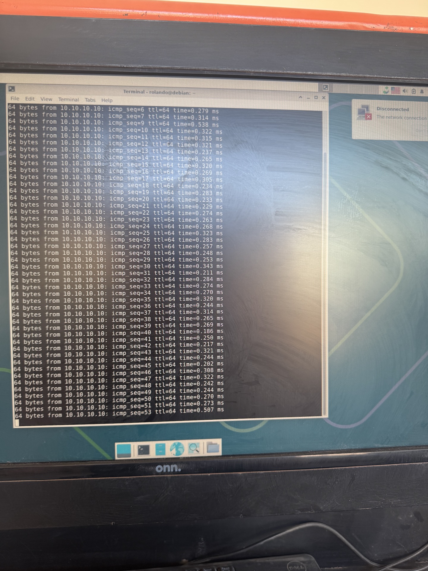
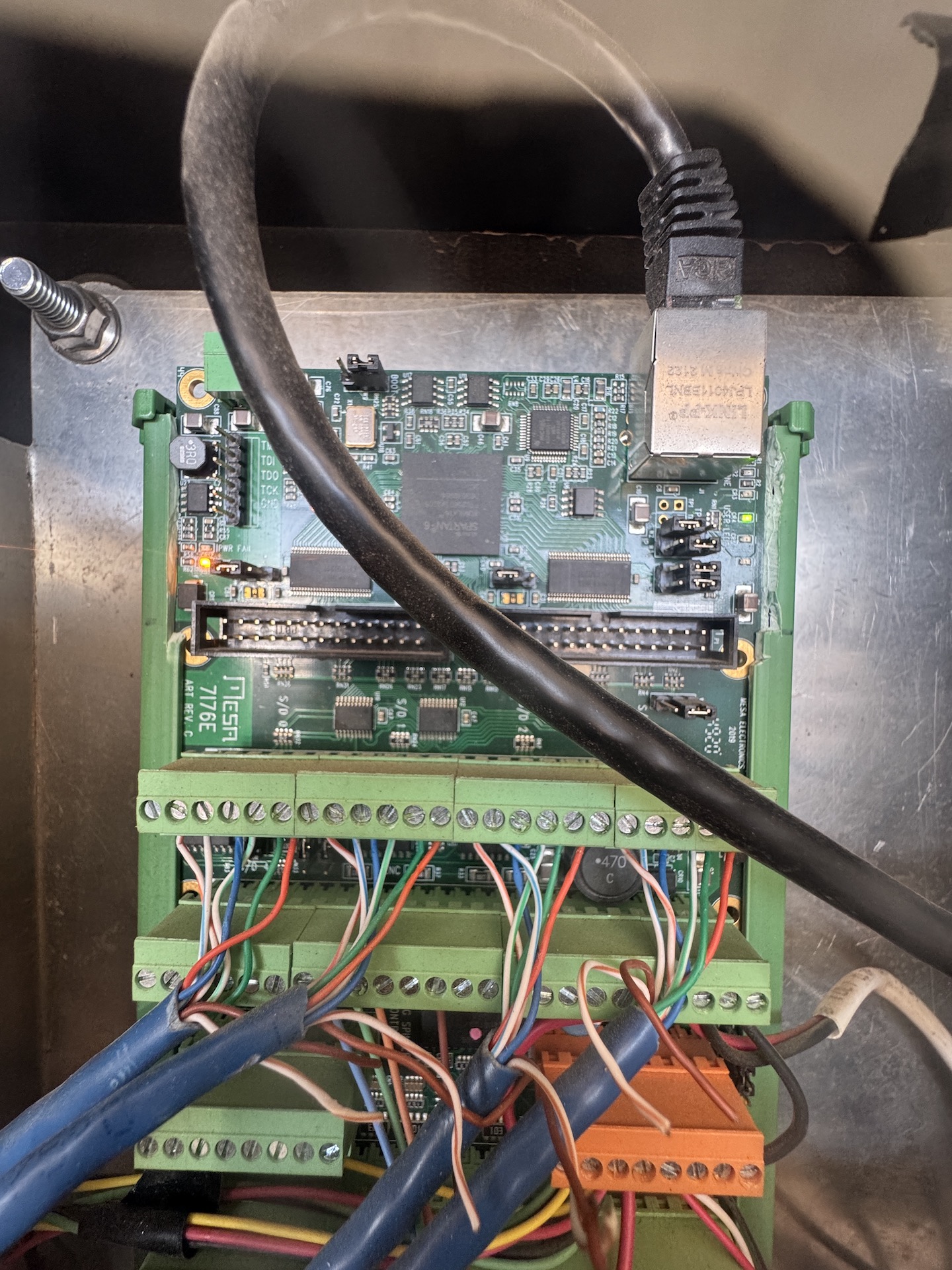
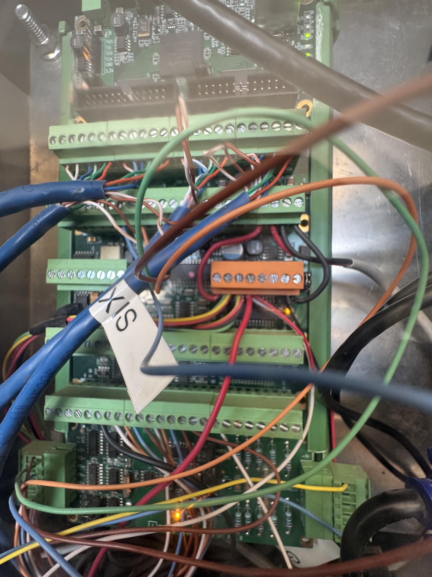
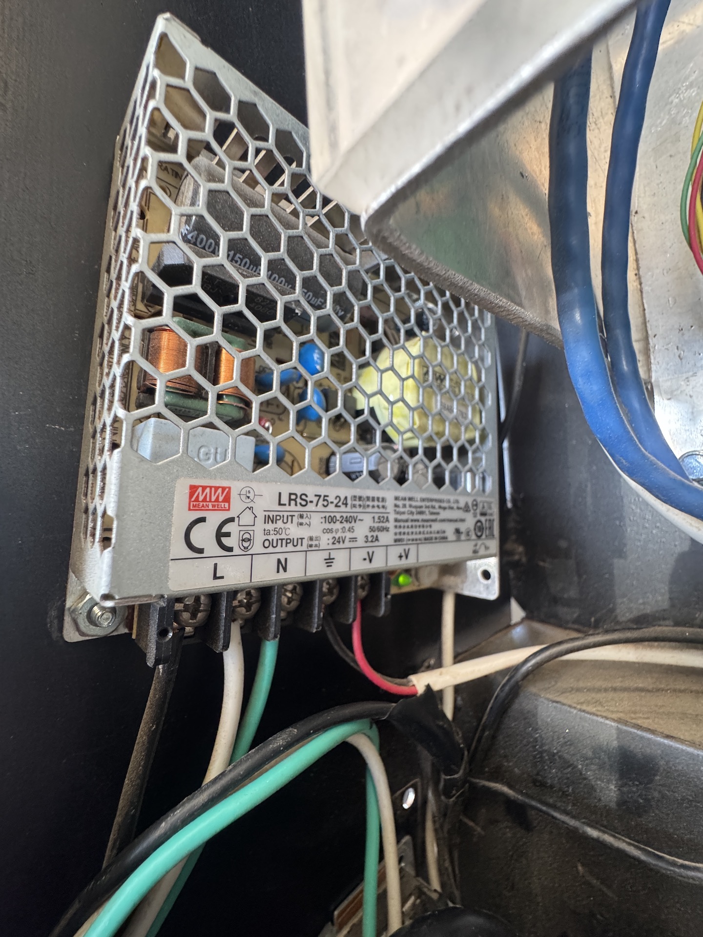
Ethernet connection to Mesa 7i76e disconnecting on its own after one minute
Category: Plasmac
- rodw
01 Jun 2026 00:34
- PCW

31 May 2026 21:18
- RMJ fabrication
- RMJ fabrication
31 May 2026 16:38
Replied by RMJ fabrication on topic Ethernet connection to Mesa 7i76e disconnecting on its own after one minute
Ethernet connection to Mesa 7i76e disconnecting on its own after one minute
Category: Plasmac
- rodw
31 May 2026 10:53
- RMJ fabrication
- RMJ fabrication
31 May 2026 01:50
Replied by RMJ fabrication on topic Ethernet connection to Mesa 7i76e disconnecting on its own after one minute
Ethernet connection to Mesa 7i76e disconnecting on its own after one minute
Category: Plasmac
- PCW
31 May 2026 00:27
- tommylight
30 May 2026 23:50
Replied by tommylight on topic Ethernet connection to Mesa 7i76e disconnecting on its own after one minute
Ethernet connection to Mesa 7i76e disconnecting on its own after one minute
Category: Plasmac
- rodw
30 May 2026 23:40
- RMJ fabrication
- RMJ fabrication
30 May 2026 22:43
Replied by RMJ fabrication on topic Ethernet connection to Mesa 7i76e disconnecting on its own after one minute
Ethernet connection to Mesa 7i76e disconnecting on its own after one minute
Category: Plasmac
- PCW
30 May 2026 21:57
- RMJ fabrication
- RMJ fabrication
30 May 2026 21:50
Replied by RMJ fabrication on topic Ethernet connection to Mesa 7i76e disconnecting on its own after one minute
Ethernet connection to Mesa 7i76e disconnecting on its own after one minute
Category: Plasmac
- RMJ fabrication
- RMJ fabrication
30 May 2026 21:22
Replied by RMJ fabrication on topic Ethernet connection to Mesa 7i76e disconnecting on its own after one minute
Ethernet connection to Mesa 7i76e disconnecting on its own after one minute
Category: Plasmac
- PCW
30 May 2026 20:37
Time to create page: 0.603 seconds