Search Results (Searched for: stepper spindle)
- ozntyr
- ozntyr
25 Sep 2025 09:04
5-Axis CNC Setup with LinuxCNC + Mesa Boards was created by ozntyr
5-Axis CNC Setup with LinuxCNC + Mesa Boards
Category: General LinuxCNC Questions
Hi everyone,I’ve been working on a CNC project for a while and I’d like some advice before committing to hardware. Here’s my situation:
- I originally built a 3-axis CNC router running on GRBL (ESP32) + a custom PCB. I used that setup for a long time and gained good experience with it.
- Later, I decided to upgrade to 5-axis by adding A and C axes to the same GRBL-based system. While it functions, I quickly discovered a limitation: ESP32 GRBL doesn’t support TCP, so the machine can’t act as a proper 5-axis system.
- Because of this, I started looking into LinuxCNC. At first I wanted to use my Raspberry Pi 5, but I read that the Pi version of LinuxCNC can’t really handle full 5-axis control.
- I then tried installing LinuxCNC on an old laptop, but since it has no parallel port, I searched for hardware solutions that use Ethernet. That’s how I found Mesa boards.
- The 7i76 series supports 5 axes and spindle control, but its encoder inputs are only for the spindle, not for axes.
- The 7i95 series seems more suitable because it supports encoder inputs for the axes as well. My thinking was that even though steppers usually work fine, it would be good to have encoder feedback to check for missed steps.
- When testing LinuxCNC setup, I couldn’t find any 7i95 options in PNCconf, which left me confused.
- My current hardware: 2.2 Nm NEMA 23 steppers with DM556 drivers on all axes (6 motors total, since Y has dual rails).
- I don’t have encoders yet, I was waiting to see which types are actually supported by the mesa boards.
- As another option, I do have a couple of 400 W Delta B3 servos, but not enough to equip all axes. I’ve considered using them if steppers turn out too weak, but that would mean buying more servos.
- My main goal with encoders is simply to check for missed steps on the steppers.
- Am I on the right track with the 7i95 + LinuxCNC setup for a 5-axis machine with encoder feedback?
- Would you recommend a different Mesa board or configuration for this?
- Are there any guides/resources for setting up a 4+ axis machine with Mesa boards and LinuxCNC?
- phew
- phew
21 Sep 2025 12:21
LCNC 2.9.5 - How to jog with a wireless xbox bt controller was created by phew
LCNC 2.9.5 - How to jog with a wireless xbox bt controller
Category: Basic Configuration
Hey,
I am trying to set up my xbox controller to jog a three axis machine (y-gantry). Using a bluetooth dongle I had to fiddle around a bit (and install xpadneo) to get the controller to connect to the system but I eventually got there and do see input when pressing buttons/moving the joysticks.
I was digging into LinuxCNC a few years ago but then life happened and I had to put the project on ice up until now. This is my first home-built CNC (wood router) and I am very new to all of this.
My goal is to be able to move the X, Y (gantry) and Z axis using the gaming controller when there is no gcode being executed.
Currently this is a parport setup and the stepper motors are not actually installed on ball screws so I do not mess up anything while testing. I am planning on switching to a mesa card in the near future.
xyyz.ini (machine basic setup)
xyyz.hal:
xbox.hal
With this setup I can see input from the controller in halshow:
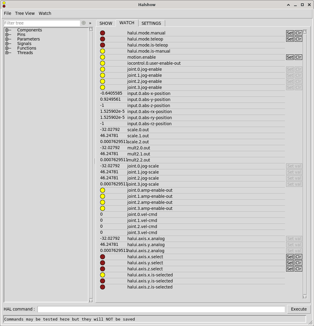
However, joint.*.vel-cmd always stays 0 and obviously the stepper motors are not spinning. Also I am not sure what mode I have to use, but I also tried setting halui.mode.manual and halui.mode.teleop using the [Set] button in halshow, but this did not change anything.
Setting it up like this will not allow the machine to start when the Xbox Controller is not connected as it expects the controller to be found. The controller will shut itself off if not being used for a certain period of time and this will also result in an error popping up in axis ui.
I think my current approach is way more complicated and clumsy than it actually needs to be, but the learning curve seems to be pretty steep for me and therefore I probably resorted to using way more AI generated code than I should have.
How do I
I am trying to set up my xbox controller to jog a three axis machine (y-gantry). Using a bluetooth dongle I had to fiddle around a bit (and install xpadneo) to get the controller to connect to the system but I eventually got there and do see input when pressing buttons/moving the joysticks.
I was digging into LinuxCNC a few years ago but then life happened and I had to put the project on ice up until now. This is my first home-built CNC (wood router) and I am very new to all of this.
My goal is to be able to move the X, Y (gantry) and Z axis using the gaming controller when there is no gcode being executed.
Currently this is a parport setup and the stepper motors are not actually installed on ball screws so I do not mess up anything while testing. I am planning on switching to a mesa card in the near future.
phew@linuxcnc:~$ sudo lsusb
Bus 001 Device 002: ID 2357:0604 TP-Link TP-Link Bluetooth USB Adapter
phew@linuxcnc:~$ sudo dkms status
hid-xpadneo/v0.9-226-ga16acb0, 6.1.0-39-rt-amd64, x86_64: installed
phew@linuxcnc:~$ sudo dmesg | grep -i xbox
[   41.033957] input: Xbox Wireless Controller as /devices/virtual/misc/uhid/0005:045E:0B13.0007/input/input16
[   41.034076] hid-generic 0005:045E:0B13.0007: input,hidraw6: BLUETOOTH HID v5.23 Gamepad [Xbox Wireless Controller] on 98:03:8e:4f:32:fd
[   41.094172] input: Xbox Wireless Controller as /devices/virtual/misc/uhid/0005:045E:0B13.0007/input/input17
[   41.094277] xpadneo 0005:045E:0B13.0007: input,hidraw6: BLUETOOTH HID v11.30 Gamepad [Xbox Wireless Controller] on 98:03:8e:4f:32:fd
[   41.094307] input: Xbox Wireless Controller Consumer Control as /devices/virtual/misc/uhid/0005:045E:0B13.0007/input/input18
[   41.094367] input: Xbox Wireless Controller Keyboard as /devices/virtual/misc/uhid/0005:045E:0B13.0007/input/input19
[   42.076531] xpadneo 0005:045E:0B13.0007: Xbox Wireless Controller [14:cb:65:c7:03:1e] connected
[   42.206305] input: Xbox Wireless Controller as /devices/virtual/misc/uhid/0005:045E:0B13.0007/input/input20
[   42.206585] xpadneo 0005:045E:0B13.0007: input,hidraw6: BLUETOOTH HID v11.30 Gamepad [Xbox Wireless Controller] on 98:03:8e:4f:32:fd
[   42.206615] input: Xbox Wireless Controller Consumer Control as /devices/virtual/misc/uhid/0005:045E:0B13.0007/input/input21
[   42.206743] input: Xbox Wireless Controller Keyboard as /devices/virtual/misc/uhid/0005:045E:0B13.0007/input/input22
[   43.189177] xpadneo 0005:045E:0B13.0007: Xbox Wireless Controller [14:cb:65:c7:03:1e] connected
xyyz.ini (machine basic setup)
# Generated by stepconf 1.1 at Thu Sep 11 20:35:55 2025
# If you make changes to this file, they will be
# overwritten when you run stepconf again

[EMC]
MACHINE = xyyz
DEBUG = 0
VERSION = 1.1

[DISPLAY]
DISPLAY = axis
EDITOR = gedit
POSITION_OFFSET = RELATIVE
POSITION_FEEDBACK = ACTUAL
ARCDIVISION = 64
GRIDS = 10mm 20mm 50mm 100mm 1in 2in 5in 10in
MAX_FEED_OVERRIDE = 1.2
MIN_SPINDLE_OVERRIDE = 0.5
MAX_SPINDLE_OVERRIDE = 1.2
DEFAULT_LINEAR_VELOCITY = 10.0
MIN_LINEAR_VELOCITY = 0
MAX_LINEAR_VELOCITY = 50.0
CYCLE_TIME = 0.100
INTRO_GRAPHIC = linuxcnc.gif
INTRO_TIME = 5
PROGRAM_PREFIX = /home/phew/linuxcnc/nc_files
INCREMENTS = 20mm 10mm 5mm 1mm .5mm .1mm .05mm .01mm .005mm

[KINS]
JOINTS = 4
KINEMATICS = trivkins coordinates=XYYZ kinstype=both

[FILTER]
PROGRAM_EXTENSION = .png,.gif,.jpg Greyscale Depth Image
PROGRAM_EXTENSION = .py Python Script
PROGRAM_EXTENSION = .nc,.tap G-Code File
png = image-to-gcode
gif = image-to-gcode
jpg = image-to-gcode
py = python

[TASK]
TASK = milltask
CYCLE_TIME = 0.010

[RS274NGC]
PARAMETER_FILE = linuxcnc.var

[EMCMOT]
EMCMOT = motmod
COMM_TIMEOUT = 1.0
BASE_PERIOD = 50000
SERVO_PERIOD = 1000000

[HAL]
HALUI = halui
HALFILE = xyyz.hal
HALFILE = custom.hal
HALFILE = xbox.hal
POSTGUI_HALFILE = postgui_call_list.hal
MDI_COMMAND = G0 X0
MDI_COMMAND = G0 Y0
MDI_COMMAND = G0 Z0
JOINT_0 = X
JOINT_1 = Y
JOINT_2 = Y
JOINT_3 = Z

[TRAJ]
COORDINATES =  X Y Y Z
LINEAR_UNITS = mm
ANGULAR_UNITS = degree
DEFAULT_LINEAR_VELOCITY = 2.50
MAX_LINEAR_VELOCITY = 25.00

[EMCIO]
EMCIO = io
CYCLE_TIME = 0.100
TOOL_TABLE = tool.tbl

[AXIS_X]
MAX_VELOCITY = 50.0
MAX_ACCELERATION = 25.0
MIN_LIMIT = -0.001
MAX_LIMIT = 800.0

[JOINT_0]
TYPE = LINEAR
HOME = 0.0
MIN_LIMIT = -0.001
MAX_LIMIT = 800.0
MAX_VELOCITY = 50.0
MAX_ACCELERATION = 1875.0
STEPGEN_MAXACCEL = 1875
SCALE = 160
FERROR = 1
MIN_FERROR = .25
HOME_SEQUENCE = 0
HOME_SEARCH_VEL = -20.0
HOME_LATCH_VEL = 2.0
HOME_OFFSET = -1.0
HOME_USE_INDEX = NO
HOME_IGNORE_LIMITS = YES

[AXIS_Y]
MAX_VELOCITY = 50.0
MAX_ACCELERATION = 25.0
MIN_LIMIT = -0.001
MAX_LIMIT = 1000.0

[JOINT_1]
TYPE = LINEAR
HOME = 0.0
MIN_LIMIT = -0.001
MAX_LIMIT = 1000.0
MAX_VELOCITY = 50.0
MAX_ACCELERATION = 1875.0
STEPGEN_MAXACCEL = 1875
SCALE = 160
FERROR = 1
MIN_FERROR = .25
HOME_SEQUENCE = 1
HOME_SEARCH_VEL = -20.0
HOME_LATCH_VEL = 2.0
HOME_OFFSET = -1.0
HOME_USE_INDEX = NO
HOME_IGNORE_LIMITS = YES

[JOINT_2]
TYPE = LINEAR
HOME = 0.0
MIN_LIMIT = -0.001
MAX_LIMIT = 1000.0
MAX_VELOCITY = 50.0
MAX_ACCELERATION = 1875.0
STEPGEN_MAXACCEL = 1875
SCALE = 160
FERROR = 1
MIN_FERROR = .25
HOME_SEQUENCE = 1
HOME_SEARCH_VEL = -20.0
HOME_LATCH_VEL = 2.0
HOME_OFFSET = -1.0
HOME_USE_INDEX = NO
HOME_IGNORE_LIMITS = YES

[AXIS_Z]
MAX_VELOCITY = 25.0
MAX_ACCELERATION = 10.0
MIN_LIMIT = -150.0
MAX_LIMIT = 0.001

[JOINT_3]
TYPE = LINEAR
HOME = 0.0
MIN_LIMIT = -150.0
MAX_LIMIT = 0.001
MAX_VELOCITY = 25.0
MAX_ACCELERATION = 1000.0
STEPGEN_MAXACCEL = 1875
SCALE = 160
FERROR = 1
MIN_FERROR = .25
HOME_SEQUENCE = 2
HOME_SEARCH_VEL = 20.0
HOME_LATCH_VEL = -2.0
HOME_OFFSET = 1.0
HOME_USE_INDEX = NO
HOME_IGNORE_LIMITS = YES
xyyz.hal:
loadrt [KINS]KINEMATICS kinstype=both
loadrt [EMCMOT]EMCMOT base_period_nsec=[EMCMOT]BASE_PERIOD servo_period_nsec=[EMCMOT]SERVO_PERIOD num_joints=[KINS]JOINTS
loadrt hal_parport cfg="1 out+in"
setp parport.0.reset-time 5000
loadrt stepgen step_type=0,0,0,0
loadrt pwmgen output_type=1

addf parport.0.read base-thread
addf stepgen.make-pulses base-thread
addf pwmgen.make-pulses base-thread
addf parport.0.write base-thread
addf parport.0.reset base-thread

addf stepgen.capture-position servo-thread
addf motion-command-handler servo-thread
addf motion-controller servo-thread
addf stepgen.update-freq servo-thread
addf pwmgen.update servo-thread

net x-home-raw parport.0.pin-11-in
net x-home-raw => joint.0.home-sw-in
#net x-home-raw => joint.0.neg-lim-sw-in
# net x-home-raw => joint.0.pos-lim-sw-in  # optional

net y0-home-raw parport.0.pin-12-in
net y0-home-raw => joint.1.home-sw-in
#net y0-home-raw => joint.1.neg-lim-sw-in

net y1-home-raw parport.0.pin-13-in
net y1-home-raw => joint.2.home-sw-in
#net y1-home-raw => joint.2.neg-lim-sw-in

net z-home-raw parport.0.pin-15-in
net z-home-raw => joint.3.home-sw-in
#net z-home-raw => joint.3.neg-lim-sw-in

setp stepgen.0.position-scale [JOINT_0]SCALE
setp stepgen.0.steplen 1
setp stepgen.0.stepspace 0
setp stepgen.0.dirhold 40000
setp stepgen.0.dirsetup 40000
setp stepgen.0.maxaccel [JOINT_0]STEPGEN_MAXACCEL
net xpos-cmd  joint.0.motor-pos-cmd => stepgen.0.position-cmd
net xpos-fb   stepgen.0.position-fb => joint.0.motor-pos-fb
net xstep     stepgen.0.step => parport.0.pin-02-out
net xdir      stepgen.0.dir  => parport.0.pin-03-out
net xenable   joint.0.amp-enable-out => stepgen.0.enable

net y-enable joint.1.amp-enable-out
net y-enable => stepgen.1.enable
net y-enable => stepgen.2.enable

setp stepgen.1.position-scale [JOINT_1]SCALE
setp stepgen.1.steplen 1
setp stepgen.1.stepspace 0
setp stepgen.1.dirhold 40000
setp stepgen.1.dirsetup 40000
setp stepgen.1.maxaccel [JOINT_1]STEPGEN_MAXACCEL
net ypos-cmd  joint.1.motor-pos-cmd => stepgen.1.position-cmd
net ypos-fb   stepgen.1.position-fb => joint.1.motor-pos-fb
net y0step    stepgen.1.step => parport.0.pin-04-out
net y0dir     stepgen.1.dir  => parport.0.pin-05-out

setp stepgen.2.position-scale [JOINT_2]SCALE
setp stepgen.2.steplen 1
setp stepgen.2.stepspace 0
setp stepgen.2.dirhold 40000
setp stepgen.2.dirsetup 40000
setp stepgen.2.maxaccel [JOINT_2]STEPGEN_MAXACCEL
net y1pos-cmd joint.2.motor-pos-cmd => stepgen.2.position-cmd
net y1pos-fb  stepgen.2.position-fb => joint.2.motor-pos-fb
net y1step    stepgen.2.step => parport.0.pin-06-out
net y1dir     stepgen.2.dir  => parport.0.pin-07-out

setp stepgen.3.position-scale [JOINT_3]SCALE
setp stepgen.3.steplen 1
setp stepgen.3.stepspace 0
setp stepgen.3.dirhold 40000
setp stepgen.3.dirsetup 40000
setp stepgen.3.maxaccel [JOINT_3]STEPGEN_MAXACCEL
net zpos-cmd joint.3.motor-pos-cmd => stepgen.3.position-cmd
net zpos-fb  stepgen.3.position-fb => joint.3.motor-pos-fb
net zstep    stepgen.3.step => parport.0.pin-08-out
net zdir     stepgen.3.dir  => parport.0.pin-09-out
net zenable  joint.3.amp-enable-out => stepgen.3.enable

net estop-out <= iocontrol.0.user-enable-out
net estop-out => iocontrol.0.emc-enable-in
xbox.hal
loadusr -W hal_input -KRAL Xbox

loadrt scale count=3
addf scale.0 servo-thread
addf scale.1 servo-thread
addf scale.2 servo-thread

setp scale.0.gain 50.0   # X
setp scale.1.gain 50.0   # Y
setp scale.2.gain 50.0   # Z

loadrt mult2 count=3
addf mult2.0 servo-thread
addf mult2.1 servo-thread
addf mult2.2 servo-thread

loadrt conv_bit_float
addf conv-bit-float.0 servo-thread

net xbox-x-raw input.0.abs-x-position => scale.0.in
net xbox-y-raw input.0.abs-y-position => scale.1.in
net xbox-z-raw input.0.abs-ry-position => scale.2.in

net xbox-x-scaled scale.0.out => mult2.0.in0
net xbox-y-scaled scale.1.out => mult2.1.in0
net xbox-z-scaled scale.2.out => mult2.2.in0

net xbox-jog-bit input.0.btn-a => conv-bit-float.0.in
net xbox-jog-float conv-bit-float.0.out => mult2.0.in1
net xbox-jog-float => mult2.1.in1
net xbox-jog-float => mult2.2.in1

net xbox-x-vel mult2.0.out => joint.0.jog-scale   # X
net xbox-y-vel mult2.1.out => joint.1.jog-scale   # Y (Y0)
net xbox-y-vel => joint.2.jog-scale                      # Y (Y1)
net xbox-z-vel mult2.2.out => joint.3.jog-scale   # Z

# Press [A]-button to enable joints
net xbox-jog-bit => joint.0.jog-enable
net xbox-jog-bit => joint.1.jog-enable
net xbox-jog-bit => joint.2.jog-enable
net xbox-jog-bit => joint.3.jog-enable

setp joint.0.jog-vel-mode TRUE
setp joint.1.jog-vel-mode TRUE
setp joint.2.jog-vel-mode TRUE
setp joint.3.jog-vel-mode TRUE

net xbox-x-vel => halui.axis.x.analog
net xbox-y-vel => halui.axis.y.analog
net xbox-z-vel => halui.axis.z.analog
With this setup I can see input from the controller in halshow:
However, joint.*.vel-cmd always stays 0 and obviously the stepper motors are not spinning. Also I am not sure what mode I have to use, but I also tried setting halui.mode.manual and halui.mode.teleop using the [Set] button in halshow, but this did not change anything.
Setting it up like this will not allow the machine to start when the Xbox Controller is not connected as it expects the controller to be found. The controller will shut itself off if not being used for a certain period of time and this will also result in an error popping up in axis ui.
I think my current approach is way more complicated and clumsy than it actually needs to be, but the learning curve seems to be pretty steep for me and therefore I probably resorted to using way more AI generated code than I should have.
How do I
- set this up correctly so the Xbox Controller input can actually controll the X, Y and Z axis?
- set this up in a way so the controller does not need to be connected in order for the machine to start and won't result in an error when the controller disconnects for some reason
- farmer_mike
- farmer_mike
12 Sep 2025 13:35 - 13 Sep 2025 01:36
Replied by farmer_mike on topic Getting (hopefully) close to an Rtelligent build
Getting (hopefully) close to an Rtelligent build
Category: EtherCAT
I have made some big progress lately. I have the limit switches and homing switches working. I also have the E stop working.
My issue is the RS750E AC servos shake quite a bit. Without the drive belts installed, the servos will sit and shake after completing a move. With the drive belts on, the system moves in the correct direction, but does so in a shaky manner.
My hypothesis is too much integral gain. I believe the problem is because I started with the stepper motor examples. Maybe there are some PID gains inside the drive that I need to configure.
I think what I need are the drive gains set with the SDO parameters inside the XML file.
Thanks for all the help
[/code]
[/code]
[/code]
My issue is the RS750E AC servos shake quite a bit. Without the drive belts installed, the servos will sit and shake after completing a move. With the drive belts on, the system moves in the correct direction, but does so in a shaky manner.
My hypothesis is too much integral gain. I believe the problem is because I started with the stepper motor examples. Maybe there are some PID gains inside the drive that I need to configure.
I think what I need are the drive gains set with the SDO parameters inside the XML file.
Thanks for all the help
###########################################################
#
# CIA 402 example snippet Hal
#
###########################################################

###########################################################
# Setup
###########################################################

loadrt [KINS]KINEMATICS
loadrt [EMCMOT]EMCMOT servo_period_nsec=[EMCMOT]SERVO_PERIOD num_joints=[KINS]JOINTS


loadusr -W lcec_conf ethercat-conf.xml
#loadusr -W /home/cnc/linuxcnc/configs/linuxcnc-cia402-single/python_control.py

loadrt lcec
loadrt cia402 count=3
loadrt pid names=0-pid,1-pid,2-pid

loadrt bitslice count=6 personality=32,32,32,32,32,32
addf bitslice.0 servo-thread
addf bitslice.1 servo-thread
addf bitslice.2 servo-thread
addf bitslice.3 servo-thread
addf bitslice.4 servo-thread
addf bitslice.5 servo-thread

loadrt conv_s32_u32 count=6
addf conv-s32-u32.0 servo-thread
addf conv-s32-u32.1 servo-thread
addf conv-s32-u32.2 servo-thread
addf conv-s32-u32.3 servo-thread
addf conv-s32-u32.4 servo-thread
addf conv-s32-u32.5 servo-thread


###########################################################
# Functions servo-thread
###########################################################

addf lcec.read-all servo-thread
addf cia402.0.read-all servo-thread
addf cia402.1.read-all servo-thread
addf cia402.2.read-all servo-thread

addf motion-command-handler servo-thread
addf motion-controller servo-thread

addf 0-pid.do-pid-calcs servo-thread
addf 1-pid.do-pid-calcs servo-thread
addf 2-pid.do-pid-calcs servo-thread

addf cia402.0.write-all servo-thread
addf cia402.1.write-all servo-thread
addf cia402.2.write-all servo-thread
addf lcec.write-all servo-thread


#########################################
#nets
#########################################
net emc-enable => iocontrol.0.emc-enable-in
sets emc-enable 1

#config


#
# Joint 0
#
setp cia402.0.csp-mode 1
setp cia402.0.pos-scale 786432


#from servo(ethercat) to cia402
net 0-statusword lcec.0.0.cia-statusword => cia402.0.statusword
net 0-opmode-display lcec.0.0.opmode-display => cia402.0.opmode-display
net 0-drv-act-pos lcec.0.0.actual-position => cia402.0.drv-actual-position
net 0-drv-act-velo lcec.0.0.actual-velocity => cia402.0.drv-actual-velocity

#from motion to cia

net 0-enable <= joint.0.amp-enable-out => cia402.0.enable
net 0-amp-fault => joint.0.amp-fault-in <= cia402.0.drv-fault
net 0-pos-cmd <= joint.0.motor-pos-cmd => cia402.0.pos-cmd
net 0-pos-fb => joint.0.motor-pos-fb <= cia402.0.pos-fb


#from cia402 to servo(ethercat)
net 0-controlword cia402.0.controlword => lcec.0.0.cia-controlword
net 0-modes-of-operation cia402.0.opmode => lcec.0.0.opmode
net 0-drv-target-pos cia402.0.drv-target-position => lcec.0.0.target-position
net 0-drv-target-velo cia402.0.drv-target-velocity => lcec.0.0.target-velocity


net my-out-0 conv-s32-u32.0.in <= lcec.0.0.digitalinputs
net my-in-0 conv-s32-u32.0.out => bitslice.0.in
net my-bit-0 bitslice.0.out-00 joint.0.neg-lim-sw-in

net my-out-0 conv-s32-u32.1.in <= lcec.0.0.digitalinputs
net my-in-1 conv-s32-u32.1.out => bitslice.1.in
net my-bit-1 bitslice.1.out-01 joint.0.pos-lim-sw-in

net my-out-0 conv-s32-u32.2.in <= lcec.0.0.digitalinputs
net my-in-2 conv-s32-u32.2.out => bitslice.2.in
net my-bit-2 bitslice.2.out-02 joint.0.home-sw-in


#
# Joint 1
#
setp cia402.1.csp-mode 1
setp cia402.1.pos-scale -786432

#from servo(ethercat) to cia402
net 1-statusword lcec.0.1.cia-statusword => cia402.1.statusword
net 1-opmode-display lcec.0.1.opmode-display => cia402.1.opmode-display
net 1-drv-act-pos lcec.0.1.actual-position => cia402.1.drv-actual-position
net 1-drv-act-velo lcec.0.1.actual-velocity => cia402.1.drv-actual-velocity

#from cia402 to servo(ethercat)
net 1-controlword cia402.1.controlword => lcec.0.1.cia-controlword
net 1-modes-of-operation cia402.1.opmode => lcec.0.1.opmode
net 1-drv-target-pos cia402.1.drv-target-position => lcec.0.1.target-position
net 1-drv-target-velo cia402.1.drv-target-velocity => lcec.0.1.target-velocity

#from motion to cia
net 1-enable <= joint.1.amp-enable-out => cia402.1.enable
net 1-amp-fault => joint.1.amp-fault-in <= cia402.1.drv-fault
net 1-pos-cmd <= joint.1.motor-pos-cmd => cia402.1.pos-cmd
net 1-pos-fb => joint.1.motor-pos-fb <= cia402.1.pos-fb


net my-out-1 conv-s32-u32.3.in <= lcec.0.1.digitalinputs
net my-in-3 conv-s32-u32.3.out => bitslice.3.in
net my-bit-3 bitslice.3.out-00 joint.1.pos-lim-sw-in

net my-out-1 conv-s32-u32.4.in <= lcec.0.1.digitalinputs
net my-in-4 conv-s32-u32.4.out => bitslice.4.in
net my-bit-4 bitslice.4.out-01 joint.1.neg-lim-sw-in

net my-out-1 conv-s32-u32.5.in <= lcec.0.1.digitalinputs
net my-in-5 conv-s32-u32.5.out => bitslice.5.in
net my-bit-5 bitslice.5.out-02 joint.1.home-sw-in


#
# Joint 2
#
setp cia402.2.csp-mode 1
setp cia402.2.pos-scale 96000

#from servo(ethercat) to cia402
net 2-statusword lcec.0.2.cia-statusword => cia402.2.statusword
net 2-opmode-display lcec.0.2.opmode-display => cia402.2.opmode-display
net 2-drv-act-pos lcec.0.2.actual-position => cia402.2.drv-actual-position
net 2-drv-act-velo lcec.0.2.actual-velocity => cia402.2.drv-actual-velocity

#from cia402 to servo(ethercat)
net 2-controlword cia402.2.controlword => lcec.0.2.cia-controlword
net 2-modes-of-operation cia402.2.opmode => lcec.0.2.opmode
net 2-drv-target-pos cia402.2.drv-target-position => lcec.0.2.target-position
net 2-drv-target-velo cia402.2.drv-target-velocity => lcec.0.2.target-velocity

#from motion to cia
net 2-enable <= joint.2.amp-enable-out => cia402.2.enable
net 2-amp-fault => joint.2.amp-fault-in <= cia402.2.drv-fault
net 2-pos-cmd <= joint.2.motor-pos-cmd => cia402.2.pos-cmd
net 2-pos-fb => joint.2.motor-pos-fb <= cia402.2.pos-fb

net 2-CCW-limit lcec.0.2.in-3 => joint.2.neg-lim-sw-in
net 2-CW-limit lcec.0.2.in-4 => joint.2.pos-lim-sw-in
net 2-in-home lcec.0.2.in-5 => joint.2.home-sw-in
net 2-in-6 lcec.0.2.in-6 => halui.estop.activate


#net spindle_speed spindle.0.speed-out => python_control.rpm_in
[code]# This config file was created 2020-08-14 17:19:37.621705 by the update_ini script
# The original config files may be found in the /home/demo/linuxcnc/configs/et-3ax/et_3ax_CIA402.old directory

[EMC]
# The version string for this INI file.
VERSION = 1.1

MACHINE = EtherCAT Machine
DEBUG = 1

[DISPLAY]
DISPLAY = axis
EDITOR = gedit

#PYVCP = pyvcp_panel.xml

# places the pyvcp panel at the bottom of the Axis window
PYVCP_POSITION = RIGHT

# Cycle time, in seconds, that display will sleep between polls
CYCLE_TIME =            0.100

# Path to help file
HELP_FILE =             doc/help.txt

# Initial display setting for position, RELATIVE or MACHINE
POSITION_OFFSET = RELATIVE
POSITION_FEEDBACK = ACTUAL
MAX_FEED_OVERRIDE = 1
# Prefix to be used
PROGRAM_PREFIX = /home/demo/linuxcnc/nc_files
INTRO_GRAPHIC = linuxcnc.gif
INTRO_TIME = 0
INCREMENTS = 1in .5in .25in .125in .0625in .025in .05in
#INCREMENTS = 5mm 1mm .5mm .1mm .05mm .01mm .005mm

[FILTER]
PROGRAM_EXTENSION = .png,.gif,.jpg Greyscale Depth Image
PROGRAM_EXTENSION = .py Python Script
png = image-to-gcode
gif = image-to-gcode
jpg = image-to-gcode
py = python
nc = /usr/bin/axis

[RS274NGC]

PARAMETER_FILE = linuxcnc.var

[EMCMOT]

EMCMOT = motmod
COMM_TIMEOUT = 1.0
BASE_PERIOD =  0
SERVO_PERIOD = 1000000

[TASK]
TASK = milltask
CYCLE_TIME = 0.005

[HAL]
HALFILE = cia402.hal
#SHUTDOWN = shutdown.hal
HALUI = halui

[HALUI]

[TRAJ]

HOME = 16 12 7
COORDINATES = XYZ
LINEAR_UNITS = in
ANGULAR_UNITS = deg
DEFAULT_LINEAR_VELOCITY = .25
MAX_LINEAR_VELOCITY = .5
MIN_LINEAR_VELOCITY = .01
DEFAULT_ANGULAR_VELOCITY = 360
MAX_ANGULAR_VELOCITY = 720
POSITION_FILE = position.txt

[EMCIO]

# Name of IO controller program, e.g., iov2 has tool changer stuff
EMCIO =         iov2

CYCLE_TIME =    0.100

# tool table file
TOOL_TABLE =    cia402.tbl
TOOL_CHANGE_POSITION = 0 0 50.8
#RANDOM_TOOLCHANGER = 1


[KINS]
JOINTS = 3
KINEMATICS = trivkins kinstype=both coordinates=xyz


[AXIS_X]
MIN_LIMIT = 0.1
MAX_LIMIT = 17.9
MAX_VELOCITY = .5
MAX_ACCELERATION = 10
BACKLASH = 0.0000

[JOINT_0]
TYPE = LINEAR
MAX_VELOCITY = .5
MAX_ACCELERATION = 10

DEADBAND = 0.01
P=1
I=0
D=0

# The values below should be 25% larger than MAX_VELOCITY and MAX_ACCELERATION
# If using BACKLASH compensation STEPGEN_MAXACCEL should be 100% larger.
# is this applicable for ethercat????
#STEPGEN_MAXVEL = 1.25
#STEPGEN_MAXACCEL = 1.25
SCALE = 1
FERROR = 200
MIN_FERROR = 50
MIN_LIMIT = 0
MAX_LIMIT = 18
HOME                    = 16
HOME_OFFSET                = 16
HOME_SEQUENCE            = 0

HOME_SEARCH_VEL = -.125
HOME_LATCH_VEL = -.125
HOME_USE_INDEX = NO
HOME_IGNORE_LIMITS        = NO


[AXIS_Y]
MIN_LIMIT = 0.1
MAX_LIMIT = 12.9
MAX_VELOCITY = .5
MAX_ACCELERATION = 10
BACKLASH = 0.0000


[JOINT_1]
TYPE = LINEAR
MAX_VELOCITY = .5
MAX_ACCELERATION = 10

DEADBAND = 0.01
P=1
I=0
D=0


# The values below should be 25% larger than MAX_VELOCITY and MAX_ACCELERATION
# If using BACKLASH compensation STEPGEN_MAXACCEL should be 100% larger.
# is this applicable for ethercat????
#STEPGEN_MAXVEL = 1.25
#STEPGEN_MAXACCEL = 1.25
STEP_SCALE = 1
FERROR = 2
MIN_FERROR = 20
MIN_LIMIT = 0
MAX_LIMIT = 13

HOME                    = 12
HOME_OFFSET                = 12
HOME_SEQUENCE            = 1

HOME_SEARCH_VEL = .125
HOME_LATCH_VEL = .125
HOME_USE_INDEX = NO
HOME_IGNORE_LIMITS        = NO


[JOINT_2]
TYPE = LINEAR
MAX_VELOCITY = .5
MAX_ACCELERATION = 10
# The values below should be 25% larger than MAX_VELOCITY and MAX_ACCELERATION
# If using BACKLASH compensation STEPGEN_MAXACCEL should be 100% larger.
# is this applicable for ethercat????
STEPGEN_MAXVEL = 1.25
STEPGEN_MAXACCEL = 1.25
STEP_SCALE = 1
FERROR = 200
MIN_FERROR = 20
MIN_LIMIT = 3.4
MAX_LIMIT = 8.1
HOME                    = 7
HOME_OFFSET                = 7
HOME_SEQUENCE            = 2

HOME_SEARCH_VEL = .125
HOME_LATCH_VEL = .125
HOME_USE_INDEX = NO
HOME_IGNORE_LIMITS    = NO


[AXIS_Z]
MIN_LIMIT = 3.5
MAX_LIMIT = 8
MAX_VELOCITY = .5
MAX_ACCELERATION = 10
BACKLASH = 0.0000
[/code]
[code][code]<masters>
  <master idx="0" appTimePeriod="1000000" refClockSyncCycles="1">


  <slave idx="0" type="generic" vid="00000A88" pid="0a880013" configPdos="true">
   <!-- Joint 0 -->
   <syncManager idx="0" dir="out"> </syncManager>
   <syncManager idx="1" dir="out"> </syncManager>
   <syncManager idx="2" dir="out">
    <pdo idx="1600">
     <pdoEntry idx="6040" subIdx="00" bitLen="16" halPin="cia-controlword" halType="u32"/>
     <pdoEntry idx="607a" subIdx="00" bitLen="32" halPin="target-position" halType="s32"/>
     <pdoEntry idx="60b8" subIdx="00" bitLen="16" halPin="touchprobefunction0" halType="bit"/>
    </pdo>
    <pdo idx="1601">
     <pdoEntry idx="6081" subIdx="00" bitLen="32" halPin="profile-velocity" halType="u32"/>
     <pdoEntry idx="6083" subIdx="00" bitLen="32" halPin="target-accel" halType="u32"/>
     <pdoEntry idx="6084" subIdx="00" bitLen="32" halPin="target-decel" halType="u32"/>
     <pdoEntry idx="6060" subIdx="00" bitLen="8" halPin="opmode" halType="s32"/>
    </pdo>
    <pdo idx="1602">
     <pdoEntry idx="60ff" subIdx="00" bitLen="32" halPin="target-velocity" halType="s32"/>
    </pdo>
   </syncManager>
   <syncManager idx="3" dir="in">
    <pdo idx="1a00">
     <pdoEntry idx="603f" subIdx="00" bitLen="16" halPin="errorcode" halType="bit"/>
     <pdoEntry idx="6041" subIdx="00" bitLen="16" halPin="cia-statusword" halType="u32"/>
     <pdoEntry idx="6061" subIdx="00" bitLen="8" halPin="opmode-display" halType="s32"/>
     <pdoEntry idx="6064" subIdx="00" bitLen="32" halPin="actual-position" halType="s32"/>
     <pdoEntry idx="60b9" subIdx="00" bitLen="16" halPin="touchprobestat" halType="bit"/>
     <pdoEntry idx="60ba" subIdx="00" bitLen="32" halPin="touchprobe1pos" halType="s32"/>
     <pdoEntry idx="60fd" subIdx="00" bitLen="32" halPin="digitalinputs" halType="s32"/>
    </pdo>
    <pdo idx="1a01">
     <pdoEntry idx="606c" subIdx="00" bitLen="32" halPin="actual-velocity" halType="s32"/>
    </pdo>
   </syncManager>
   <dcConf assignActivate="300" sync0Cycle="1000000"/>
  </slave>


  <slave idx="1" type="generic" vid="00000A88" pid="0a880013" configPdos="true">
   <!-- Joint 1 -->
   <syncManager idx="0" dir="out"> </syncManager>
   <syncManager idx="1" dir="out"> </syncManager>
   <syncManager idx="2" dir="out">
    <pdo idx="1600">
     <pdoEntry idx="6040" subIdx="00" bitLen="16" halPin="cia-controlword" halType="u32"/>
     <pdoEntry idx="607a" subIdx="00" bitLen="32" halPin="target-position" halType="s32"/>
     <pdoEntry idx="60b8" subIdx="00" bitLen="16" halPin="touchprobefunction0" halType="bit"/>
    </pdo>
    <pdo idx="1601">
     <pdoEntry idx="6081" subIdx="00" bitLen="32" halPin="profile-velocity" halType="u32"/>
     <pdoEntry idx="6083" subIdx="00" bitLen="32" halPin="target-accel" halType="u32"/>
     <pdoEntry idx="6084" subIdx="00" bitLen="32" halPin="target-decel" halType="u32"/>
     <pdoEntry idx="6060" subIdx="00" bitLen="8" halPin="opmode" halType="s32"/>
    </pdo>
    <pdo idx="1602">
     <pdoEntry idx="60ff" subIdx="00" bitLen="32" halPin="target-velocity" halType="s32"/>
    </pdo>
   </syncManager>
   <syncManager idx="3" dir="in">
    <pdo idx="1a00">
     <pdoEntry idx="603f" subIdx="00" bitLen="16" halPin="errorcode" halType="bit"/>
     <pdoEntry idx="6041" subIdx="00" bitLen="16" halPin="cia-statusword" halType="u32"/>
     <pdoEntry idx="6061" subIdx="00" bitLen="8" halPin="opmode-display" halType="s32"/>
     <pdoEntry idx="6064" subIdx="00" bitLen="32" halPin="actual-position" halType="s32"/>
     <pdoEntry idx="60b9" subIdx="00" bitLen="16" halPin="touchprobestat" halType="bit"/>
     <pdoEntry idx="60ba" subIdx="00" bitLen="32" halPin="touchprobe1pos" halType="s32"/>
     <pdoEntry idx="60fd" subIdx="00" bitLen="32" halPin="digitalinputs" halType="s32"/>
    </pdo>
    <pdo idx="1a01">
     <pdoEntry idx="606c" subIdx="00" bitLen="32" halPin="actual-velocity" halType="s32"/>
    </pdo>
   </syncManager>
   <dcConf assignActivate="300" sync0Cycle="1000000"/>
  </slave>

     <!-- Joint 2 -->
    <slave idx="2" type="generic" vid="00000a88" pid="0a880002" configPdos="true">
      <dcConf assignActivate="300" sync0Cycle="*1" sync0Shift="0"/>
      <sdoConfig idx="2000" subIdx="0"><sdoDataRaw data ="88 13"/></sdoConfig>  <!-- Max motor current (5.0) -->
      <sdoConfig idx="2007" subIdx="3"><sdoDataRaw data ="01"/></sdoConfig>     <!-- Input 3 - CCW Limit -->
      <sdoConfig idx="2007" subIdx="4"><sdoDataRaw data ="02"/></sdoConfig>     <!-- Input 4 - CW Limit -->
      <sdoConfig idx="2007" subIdx="5"><sdoDataRaw data ="03"/></sdoConfig>     <!-- Input 5 - Home Function -->
      <sdoConfig idx="2007" subIdx="6"><sdoDataRaw data ="05"/></sdoConfig>     <!-- Input 6 - Emergency Stop -->
      <sdoConfig idx="2011" subIdx="0"><sdoDataRaw data ="01 00"/></sdoConfig>  <!-- Closed loop -->
      <sdoConfig idx="6098" subIdx="0"><sdoDataRaw data ="11 00"/></sdoConfig>  <!-- Home mode 17 -->
      <sdoConfig idx="607C" subIdx="0"><sdoDataRaw data ="00 00"/></sdoConfig>  <!-- Home offset 0  -->
      <sdoConfig idx="609A" subIdx="0"><sdoDataRaw data ="F4 01"/></sdoConfig>  <!-- Home accelleration 500 -->
      <sdoConfig idx="6099" subIdx="01"><sdoDataRaw data ="C4 09"/></sdoConfig>  <!-- Home fast speed 2500-->
      <sdoConfig idx="6099" subIdx="02"><sdoDataRaw data ="F4 01"/></sdoConfig>  <!-- Home slow speed 500 -->
      <syncManager idx="2" dir="out">
        <pdo idx="1600">
          <pdoEntry idx="6040" subIdx="00" bitLen="16" halPin="cia-controlword" halType="u32"/>
          <pdoEntry idx="6060" subIdx="00" bitLen="8" halPin="opmode" halType="s32"/>
          <!-- Target Position -->
          <pdoEntry idx="607A" subIdx="00" bitLen="32" halPin="target-position" halType="s32"/>
          <!-- Target Velocity -->
          <pdoEntry idx="60FF" subIdx="00" bitLen="32" halPin="target-velocity" halType="s32"/>
          <!-- Digtial Outputs (manufacturer's extension ECT86/ECT60)-->
          <pdoEntry idx="204A" subIdx="0" bitLen="16" halType="complex">
            <complexEntry bitLen="1" halPin="out-1" halType="bit"/>
            <complexEntry bitLen="1" halPin="out-2" halType="bit"/>
            <complexEntry bitLen="14"/>
          </pdoEntry>
        </pdo>
      </syncManager>
      <syncManager idx="3" dir="in">
        <pdo idx="1a00">
          <pdoEntry idx="6041" subIdx="00" bitLen="16" halPin="cia-statusword" halType="u32"/>
          <pdoEntry idx="6061" subIdx="00" bitLen="8" halPin="opmode-display" halType="s32"/>
          <pdoEntry idx="6064" subIdx="00" bitLen="32" halPin="actual-position" halType="s32"/>
          <pdoEntry idx="606C" subIdx="00" bitLen="32" halPin="actual-velocity" halType="s32"/>
          <pdoEntry idx="6077" subIdx="00" bitLen="32" halPin="actual-torque" halType="s32"/>
          <!-- Digtial_inputs (cia402 compatible) -->
          <pdoEntry idx="60FD" subIdx="0" bitLen="32" halType="complex">
            <complexEntry bitLen="1" halPin="CW-limit" halType="bit"/>
            <complexEntry bitLen="1" halPin="CCW-limit" halType="bit"/>
            <complexEntry bitLen="1" halPin="in-home" halType="bit"/>
            <complexEntry bitLen="13"/>
            <complexEntry bitLen="1" halPin="in-1" halType="bit"/>
            <complexEntry bitLen="1" halPin="in-2" halType="bit"/>
            <complexEntry bitLen="1" halPin="in-3" halType="bit"/>
            <complexEntry bitLen="1" halPin="in-4" halType="bit"/>
            <complexEntry bitLen="1" halPin="in-5" halType="bit"/>
            <complexEntry bitLen="1" halPin="in-6" halType="bit"/>
            <complexEntry bitLen="10"/>
          </pdoEntry>
        </pdo>
      </syncManager>
    </slave>


  </master>
</masters>
[/code]
- Martin.L
- Martin.L
06 Sep 2025 12:18
Replied by Martin.L on topic Stepperonline A6-1000EC driver
Stepperonline A6-1000EC driver
Category: EtherCAT
replace x with your servo/spindle index
net s-vel-cmd <= spindle.0.speed-out
net s-vel-cmd => cia402.x.velocity-cmd
You will need csp mode 0 :
setp cia402.5.csp-mode 0
setp cia402.5.pos-scale 1
net s-vel-cmd <= spindle.0.speed-out
net s-vel-cmd => cia402.x.velocity-cmd
You will need csp mode 0 :
setp cia402.5.csp-mode 0
setp cia402.5.pos-scale 1
- Rookie0
- Rookie0
01 Sep 2025 11:44
hope it helps.
Replied by Rookie0 on topic Stepperonline A6-1000EC driver
Stepperonline A6-1000EC driver
Category: EtherCAT
# spindle.hal
# use cia402 comp.  link: https://github.com/dbraun1981/hal-cia402
loadrt cia402 names=cia-s
addf cia-s.read-all           servo-thread
addf cia-s.write-all          servo-thread
# value = resolution_servo_encoder ÷ 60
# if gearbox exists, then * reduction_ratio(input:ouput)
setp cia-s.velo-scale 800
net s-statusword      <= lcec.0.N.cia-statusword   => cia-s.statusword
net s-opmode-display  <= lcec.0.N.opmode-display   => cia-s.opmode-display
net s-drv-act-velo    <= lcec.0.N.actual-velocity  => cia-s.drv-actual-velocity
net s-controlword     <= cia-s.controlword         => lcec.0.N.cia-controlword
net s-opmode          <= cia-s.opmode              => lcec.0.N.opmode
net s-drv-target-velo <= cia-s.drv-target-velocity => lcec.0.N.target-velocity
net s-enable          <= spindle.0.on              => cia-s.enable
net s-velo-fb         <= cia-s.velocity-fb         => spindle.0.speed-in
net s-velo-cmd        <= spindle.0.speed-out       => cia-s.velocity-cmd
hope it helps.
- russkinch

01 Sep 2025 11:14
Stepperonline A6-1000EC driver was created by russkinch
Stepperonline A6-1000EC driver
Category: EtherCAT
Hi again. I have sorted the power issue (manual was no help at all). Now, I have it set to Linuxcnc using ethercat. It is all communication etc. I want to run the servo as a spindle motor so just have the target-velocity (60FE). How do I create the 'pins' to tell the drive to turn at say 1000rpm with an M3 command is given. I have done the many times using a VFD (much easier but space and weight limits force me to use a servo).
I am soooo out of my depth here, any help is always hugely appreciated. (I have already looked through the various threads and found no help after hours of scrolling)
I am soooo out of my depth here, any help is always hugely appreciated. (I have already looked through the various threads and found no help after hours of scrolling)
- Gautham
- Gautham
29 Aug 2025 02:43
Replied by Gautham on topic Connecting my 7i96s to the VFD
Connecting my 7i96s to the VFD
Category: Driver Boards
Omg it worked!!! Thank you so much PCW not only did you spoon feed me on how to get my 7i96s to run my spindle but you also helped me get all my steppers working with the BoB. Thank you so much
- russkinch
28 Aug 2025 09:07
Stepperonline A6-1000EC driver was created by russkinch
Stepperonline A6-1000EC driver
Category: EtherCAT
Hi, I am creating a custom machine for work and really really need help. I am using the above driver with a 1000w servo motor for the spindle. I have installed ethercat and configured. I have downloaded the xml file for the drive from stepperonline. I have created a hal file that loads lcec and the xml file. But when I start linuxcnc is stops with an error saying lcec exited. How can I use this to drive the spindle. I don't need limits or probes or anything, Just speed.
I am really out of my depth here as I normally use a 3ph and vfd but space and weight does not permit this on the machine I am making.
Thanks
Russell
I am really out of my depth here as I normally use a 3ph and vfd but space and weight does not permit this on the machine I am making.
Thanks
Russell
- lj
- lj
26 Aug 2025 06:05
Replied by lj on topic ESP32 HAL2UDP setup for linux CNC noob.
ESP32 HAL2UDP setup for linux CNC noob.
Category: Computers and Hardware
Hello, I just started working on the linuxcnc esp32 W5500 setup and I ran into some issues.
1. Hardware: Rpi4 8gb with linuxcnc 2.8.4, W5500, Esp32 Wroom
2. Esp firmware: hal2udp pwm
3. Motion: open loop stepper with TB6600 Driver
Issues
1. activation of spindle or flood no voltage change on esp32 pins 4 or 25.
2. joint follow error all axis3. My stepper is enable without the enable pin connection (I'm not even sure what pin to use for enable/disable on the esp32-the pin out from the read file doesn't show what pin to use.
3. udp.stepgen.1.enable (error doesn't exsist) (My assumption is that because the udp.comp file doesnt show the param or pin) maybe I'm missing something
4. is the Pid function only used for closed loop steppers to accurately determine movement
I attached my hal and ini files
thanks for the help
- rhscdn
- rhscdn
14 Aug 2025 03:07 - 14 Aug 2025 03:13
Axyz retrofit - spindle wiring 7i96 was created by rhscdn
Axyz retrofit - spindle wiring 7i96
Category: CNC Machines
I think I have wrapped my head around my stepper motor and limit switch wiring. Regarding the spindle, I have a few questions:
The inverter is a woods eTrac x2c and the manual offers a nearly overwhelming number of options. I was never able to see the spindle working with the stock
AMC controller. I have attached the relevant table from the inverter manual and it seems like I should be able to use the analog spindle interface to provide 0-5vdc signal for speed control (vin). Do I simply use inputs on the 7i96 to conteol fwd/rev and a ground connected to the inverter common? Is that all there is to it?
The original wiring from the AMC controller to the inverter is somewhat different and it isn’t obvious that the AMC was actually able to control the spindle speed. It is connected to use 4 preset spindle speeds and the AMC has wires indicating an acceleration/deceleration signal, as well as some connections to NO and RCM.
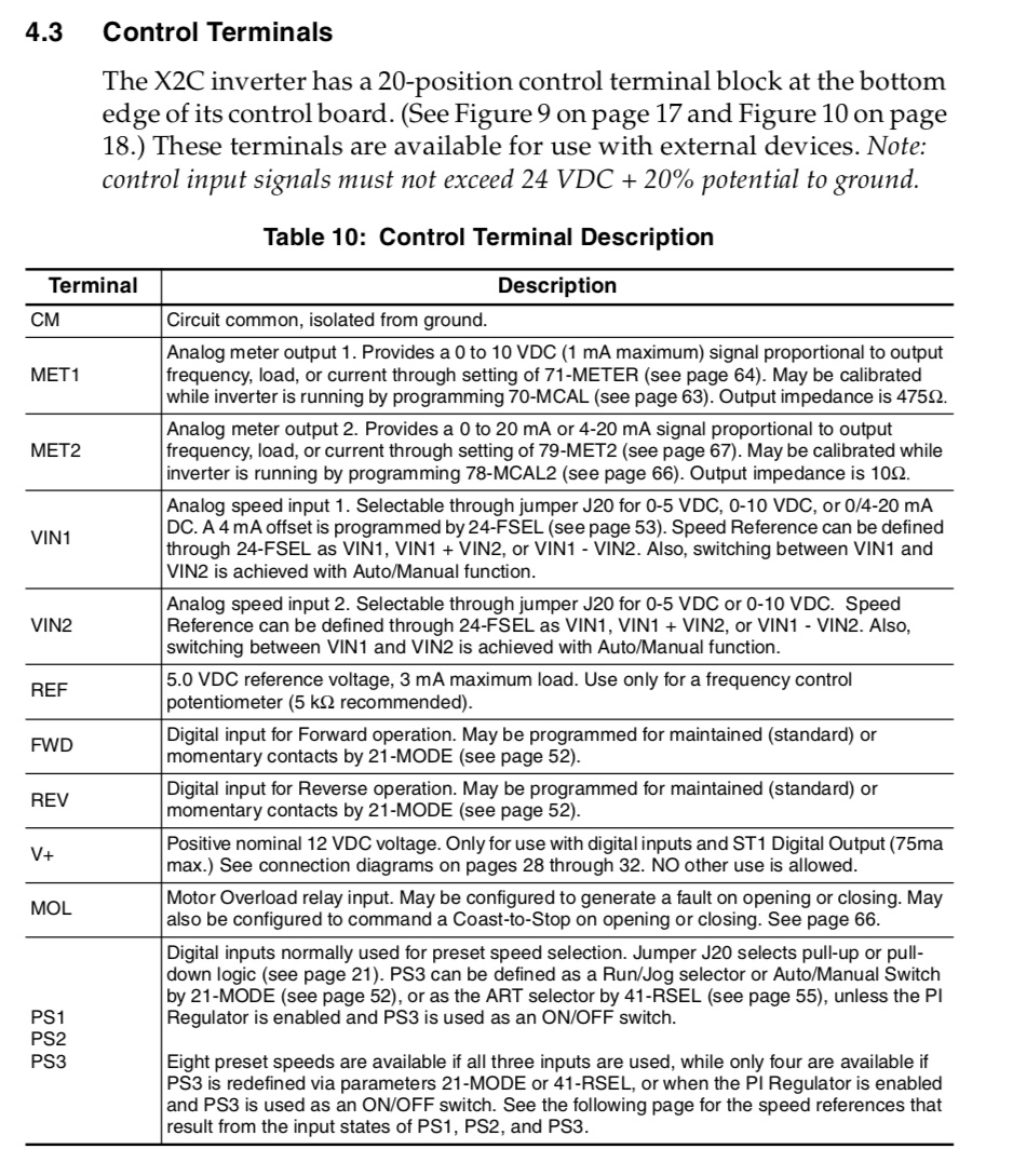
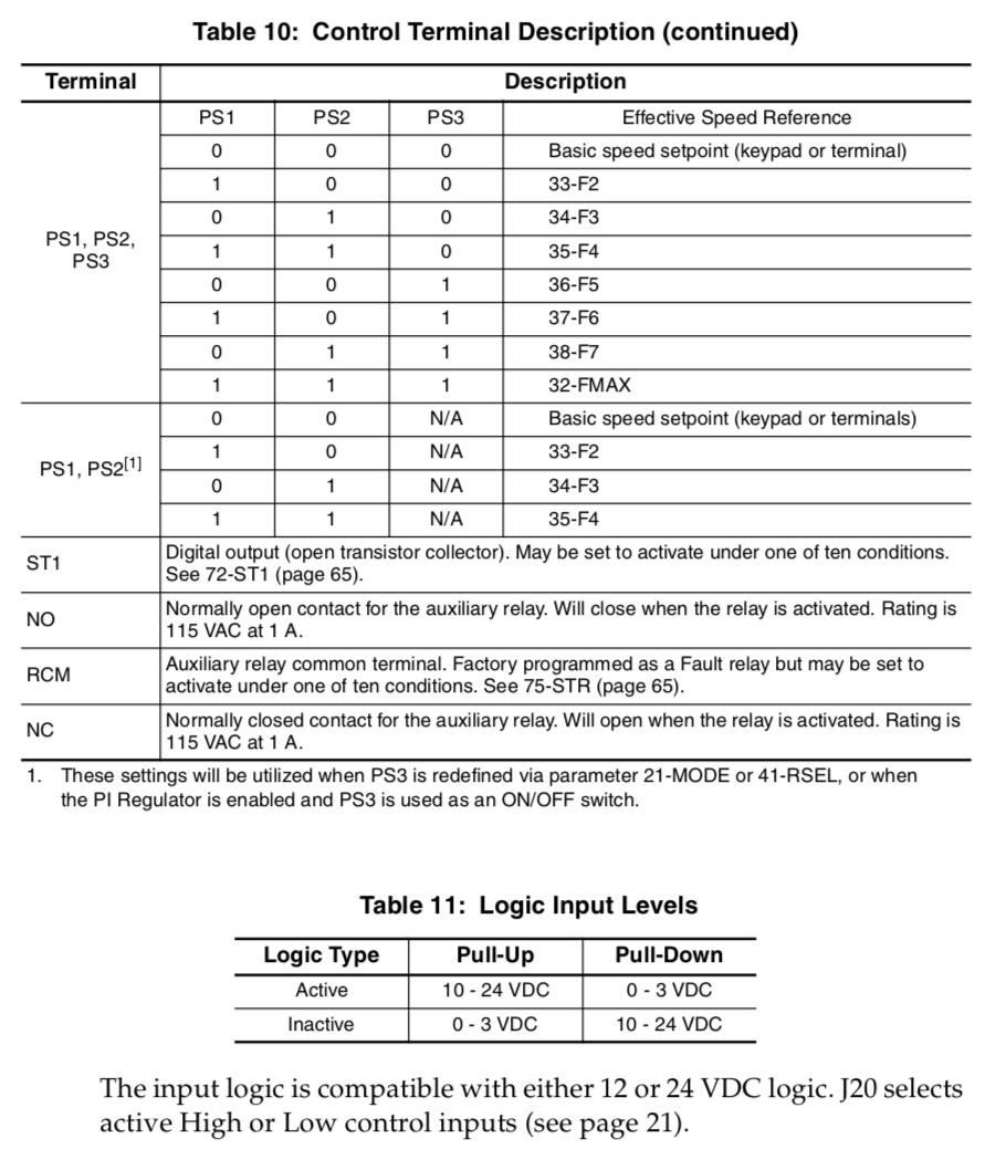
- hitchhiker
- hitchhiker
13 Aug 2025 15:35
Replied by hitchhiker on topic ECMO VMC100 Retrofit with Carousel/Toolchanger
ECMO VMC100 Retrofit with Carousel/Toolchanger
Category: Milling Machines
sry for delay.
i have now the whole machine running with the original controller.
all works.. steppers,maindrive, all sensors and the spindleencoder.
in the next days i link up my raspberry pi 4 with a 7i92.
why the rasp? its easier for me instead a notebook.. i have the machine in my garage not in my basement...
if all works and linked to the mesa and is in my linuxcnc i came back.
parallel i would build a small model for the toolchanger to play in the apartment with the toolchanger carousel stuff.
thanks
- juergen-home
- juergen-home
13 Aug 2025 09:37 - 13 Aug 2025 09:40
Replied by juergen-home on topic "pwm/dir" (Out1) switches for spindle CCW
"pwm/dir" (Out1) switches for spindle CCW
Category: Basic Configuration
At the end it was easier for me to compile a new bit file without the pwm/dir (I/O 07 PIN 17) and use it as a GPIO. It is working now.
Many thanks to you Peter!
Another question is about my "26 HDR" internal port of the 6i25 , I wanted to do my own encoder pcb but now I found a used 7I52S.
How to modify my vhd-file to do so and how should the cable from 26 HDR 6i25 to the 50 HDR 7I52S look like?
I don't now if I can use all functionality of the 7I52S but at least the 6 encoders and the rest filled with (stepper)outputs?
Should I open a new thread for this?
- konrad
- konrad
05 Aug 2025 15:24
Replied by konrad on topic prevent jog limit error
prevent jog limit error
Category: General LinuxCNC Questions
I made the config with PnCconf and only slightly changed to to account for probe basic interface.
the inductive endstops are mounted on the traveling part of the axis and there are metal stops at each end of the travel.
the machine has the following specs:
Machine Specs:
X460, Y750mm, Z160
20mm linear rails
10mm pitch ballscrews, 20mm diameter
Construction: aluminum profiles bolted to 12mm steel plates, welded gantry sides
Motors: Y-axis 6.8Nm stepper, Z + X-axis 3Nm stepper
Drives: DM556 V1 48v
Spindle: 24K RPM 2.2kW ER20
inductive endstops
good latency values mostly sub 3000ns servo
Time to create page: 0.705 seconds