Search Results (Searched for: )
- webbyguy
- webbyguy
21 Feb 2025 18:45
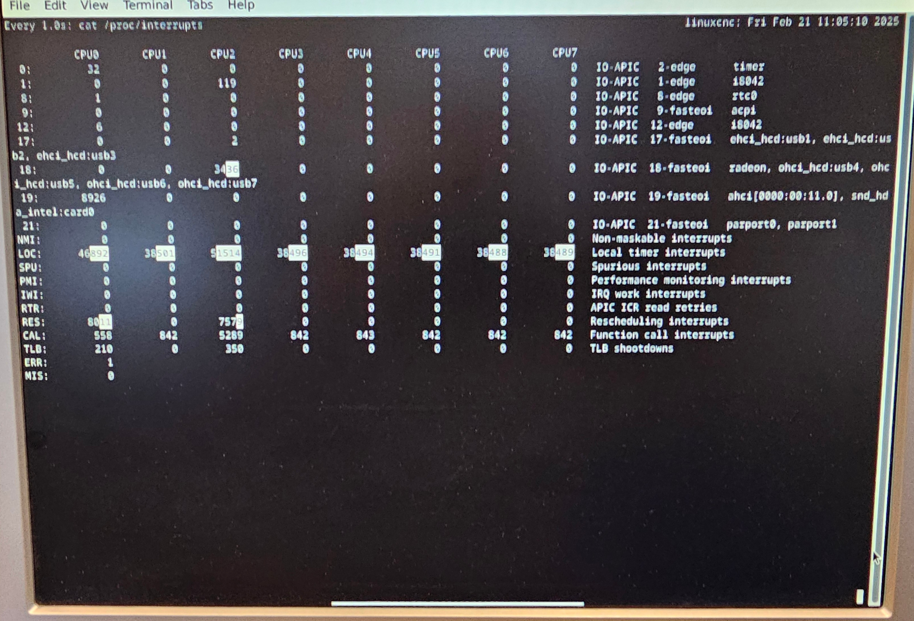
Replied by webbyguy on topic Can't eek out that last bit of jitter
Can't eek out that last bit of jitter
Category: General LinuxCNC Questions
- Sziggy_NC
- Sziggy_NC
21 Feb 2025 17:34
Replied by Sziggy_NC on topic Proof reading please. "unknown control command in o word"
Proof reading please. "unknown control command in o word"
Category: O Codes (subroutines) and NGCGUI
- denhen89

21 Feb 2025 17:06
- Aciera

21 Feb 2025 16:54 - 21 Feb 2025 16:55
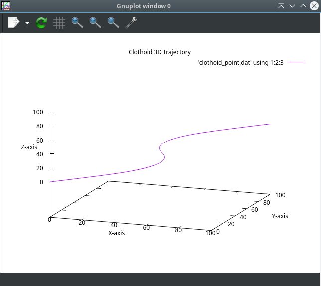
Replied by Aciera on topic scurve trajectory planner
scurve trajectory planner
Category: General LinuxCNC Questions
- tommylight

21 Feb 2025 15:40
Replied by tommylight on topic Elumatec SBZ 130/01 retrofit
Elumatec SBZ 130/01 retrofit
Category: CNC Machines
- Lcvette

21 Feb 2025 15:34
Replied by Lcvette on topic Setting up Probe Basic on my machine questions and issues
Setting up Probe Basic on my machine questions and issues
Category: QtPyVCP
- tommylight
21 Feb 2025 15:18
Replied by tommylight on topic Building a 3-axis plasma table with mesa 7i96s, THCad-2 and nema23 steppers
Building a 3-axis plasma table with mesa 7i96s, THCad-2 and nema23 steppers
Category: Show Your Stuff
- JuFu
- JuFu
21 Feb 2025 15:12
- tommylight
21 Feb 2025 15:11
Replied by tommylight on topic motor-0-position error beim Abbremsen aus 4-7,5 m/min
motor-0-position error beim Abbremsen aus 4-7,5 m/min
Category: Deutsch
- PCW

21 Feb 2025 15:07 - 21 Feb 2025 15:09
Replied by PCW on topic Mesa 7i97T + 7i84 + 7i78 configuration
Mesa 7i97T + 7i84 + 7i78 configuration
Category: General LinuxCNC Questions
- Grotius

21 Feb 2025 15:03
Replied by Grotius on topic scurve trajectory planner
scurve trajectory planner
Category: General LinuxCNC Questions
- tommylight
21 Feb 2025 14:59 - 21 Feb 2025 15:00
Replied by tommylight on topic 7I97T joint following error
7I97T joint following error
Category: General LinuxCNC Questions
- PCW
21 Feb 2025 14:57
Replied by PCW on topic motor-0-position error beim Abbremsen aus 4-7,5 m/min
motor-0-position error beim Abbremsen aus 4-7,5 m/min
Category: Deutsch
- PCW
21 Feb 2025 14:48
Replied by PCW on topic 7I97T joint following error
7I97T joint following error
Category: General LinuxCNC Questions
- FabianB
21 Feb 2025 14:05
Replied by FabianB on topic scurve trajectory planner
scurve trajectory planner
Category: General LinuxCNC Questions
Time to create page: 0.542 seconds