Advanced Search

Search Results (Searched for: )

  • besriworld
  • besriworld
14 Aug 2024 15:52
Replied by besriworld on topic OLD Lathe conversion to a CNC

OLD Lathe conversion to a CNC

Category: Turning

Thank you! Yes, I also use it as a control panel.
OK, no problem!
  • Todd Zuercher
  • Todd Zuercher's Avatar
14 Aug 2024 15:41
Replied by Todd Zuercher on topic Configuring a dual stage axis

Configuring a dual stage axis

Category: Advanced Configuration

I think it could be done in multiple ways. I'm sure you should be able to find some configuration examples out there where people have set up Linuxcnc to control knee mills with both the quill and knee contributing to the Z axis position, this would be nearly identical.

It might be better to simply do it using X and U axis, where U would be the extra stage mounted on the X. This set up would give you better control over when and how each axis is used. Alternatively you could simply use a Kinematics model were X is the sum of the two X axis joints, but this might give you less control over when or how each joint contributed to the position and movement of X.

It may even be possible to configure it using a custom Kinematics where the X-axis = joint0 + joint3 and the U-axis = joint3. Allowing you to use U commands to control the extra stage's position, but still have it automatically contribute to the final X position.

(I have never actually tried any of this myself.)

All that said, is this really a good idea? Adding a lot of cantilevered forces and movement beyond the machine's designed structure could have less than desirable results (such as magnifying/multiplying tolerance errors and greatly reduced rigidity.)
  • PCW
  • PCW's Avatar
14 Aug 2024 15:24
Replied by PCW on topic OLD Lathe conversion to a CNC

OLD Lathe conversion to a CNC

Category: Turning

Since the 7I73 was designed for control panels and not direct machine control
it does not automatically disable outputs on a fault. I suppose that feature could
be added but it might make more sense to use a 7I84/7I84U in that case.
  • mighty_mick
  • mighty_mick's Avatar
14 Aug 2024 14:59

How can I modify trivkins.c? (and also other kinematics files)

Category: General LinuxCNC Questions

Hello winyk. I've read your post, and there are few things i wanna mention.

I've developed custom kinematics module for my machine a while ago. Since you are starter, i suggest you to learn HAL layer of LinuxCNC first.
HAL layer is nothing but modules that run at background in while loop, with some sleep. Don't consider this layer as a software layer, it is actually a system that gives you ability to configure your modules, make them able to communicate with each other and allows you to collaborate across modules. In while loop, they checks some conditions, some values etc. and do the work. These modules are named as 'hal component'.

At the core of LinuxCNC, there is a motion hal component. You can check it in the documentation given below:

--> linuxcnc.org/docs/devel/html/man/man9/motion.9.html

This hal component is responsible for interpreting G-code commands and converting them into real-time control signals for machine's hardware. When you give "G90 G0 X10" command,
this is the component which gets 10 value near X and convert it to control signals for motor controller. This conversion uses your kinematics module. Your kinematics module is also a hal component, and the starter script loads it at the beginning. If you check your hal file, you are gonna see some lines like below:


...
...
...
loadrt trivkins
...
...
loadrt motmod servo_period_nsec=<value_from_your_ini_file> num_joints=<value_from_your_ini_file> tp=tp kins=<value_from_your_ini_file>

If you know what ini file format is, these lines gonna look like below.

...
...
...
loadrt trivkins
...
...
loadrt [EMCMOT]EMCMOT servo_period_nsec=[EMCMOT]SERVO_PERIOD num_joints=[TRAJ]AXES tp=tp kins=[KINEMATICS]KINEMATICS


Since you are giving the file name of your kinematics module in your .ini file like below:
[KINEMATICS]
KINEMATICS=mykins

The motmod hal component uses your kinematics component to make the calculations.

After you run "halcompile --install mykins.comp" command, the halcompile exe does these steps given below:

1. Convert .comp file to appropriate .c file
2. Compile generated .c file with system's compiler, generate a shared library (.so file)
3. Locate that .so file in /usr/lib/linuxcnc/rt-preempt/ directory.

Since you are new in C programming, you need to learn basic flow of compilation of a .c source file. You need to check what is .so file, how it can be used etc. to understand concept. The key thing you need to know is, you are generating a calculation module which exports some symbols with names as 'kinematicsInverse, kinematicsForward, .. etc.', you are locating it in the system's directory. After that, during the start of LinuxCNC, it loads motion hal component with that hal component. So the conversion and calculation of machine movement is being calculated by your code. There are so many things you need to know, but this is a basic flow.

If you wanna change the direction of your X axis, you need to change kinematicsInverse function only. The j variable is responsible for generating physical coordinates. You are getting commanded value from const EmcPose * pos variable, which is your commanded coordinate of machine, and forwarding it to physical value. This is the point that you give 10 and make it -10. So, don't change both of them to negative, change only 'kinematicsInverse' to negative. If you do this, hopefully you are gonna see your "G90 G0 X10" command is resulted as X=-10. If i am wrong, maybe i need to remember some things.

I developed some kinematics module to fix geometrical errors of my machine(squareness, straightness) a while ago. I was adding extra moves to X,Y,Z axises according to each other to neutralize the physical oscillation that one makes along any axis. There are different topics that you can use this kinematics module, but this is the core flow. If you have any other questions, i would be happy to discuss them.


Don't forget, if you are trying to change kinematics module, you need to change your ini file. Check the given link below:

--> linuxcnc.org/docs/html/config/ini-config.html#sub:ini:sec:kins

If you don't change your ini file, your hal component can't be loaded. I assume the reason that you didn't get the right result is giving negative value in both reverse and forward functions, but i can be wrong, so don't forget to check your ini and hal files.
  • Todd Zuercher
  • Todd Zuercher's Avatar
14 Aug 2024 14:12
Replied by Todd Zuercher on topic LED to indicate M3/M5 status

LED to indicate M3/M5 status

Category: GladeVCP

For the 2nd option. To display an image instead of Hal_LED's small colored circle or box, the simple answer is you can't. You must use a different widget to do this. You could use a GtkImage widget to display your images for spindle ON and OFF, then use your Python handler file to define what images are displayed and create the nessisary hal pin to select between them.

I've done something similar to this, but more complicated for the spindles on a machine I've set up. On that machine I have multiple spindles controled by Modbus, and I set up a series of GTK Images to display the status of each of them. It uses S32 hal pins to display one of about a dozen different images for each VFD, such as "Com Error", "Run", "Stop", "Accel", "Decel". "Fault"...
  • tommylight
  • tommylight's Avatar
14 Aug 2024 13:45
Replied by tommylight on topic OLD Lathe conversion to a CNC

OLD Lathe conversion to a CNC

Category: Turning

You should ask that in the "driver boards" section of the forum as i am not sure PCW monitors this side of the forum, well i am sure he does sometimes, but not sure if always.
  • arijitdutta
  • arijitdutta
14 Aug 2024 13:38
Replied by arijitdutta on topic PnCConf USB Jogging Problem

PnCConf USB Jogging Problem

Category: PnCConf Wizard

Update: 
I was finally able to go around the issue I was facing. Since the halmeter was showing up blank, one can go into the terminal and type :

halrun
loadusr -W hal_input -KRAL Gamepad ((( Gamepad is the unique code that my controller has, others might be different )))
loadusr halmeter

The halmeter shows up and gives the input pin status.
  • Todd Zuercher
  • Todd Zuercher's Avatar
14 Aug 2024 13:32
Replied by Todd Zuercher on topic LED to indicate M3/M5 status

LED to indicate M3/M5 status

Category: GladeVCP

If all you want is an LED indicator, then yes, simply, connecting the hal pin "spindle.0.on" to your your Glade Hal_Led's hal input pin in a post gui hal file would be all you would need to do.

If you are asking how to make the Hal_LED display a large red image that says "Spindle OFF", that is slightly more complicated.
  • JT
  • JT's Avatar
14 Aug 2024 12:59
Replied by JT on topic Flexible GUI

Flexible GUI

Category: Other User Interfaces

Flex has added a FSC.
 
JT
  • besriworld
  • besriworld
14 Aug 2024 12:34 - 14 Aug 2024 12:35
Replied by besriworld on topic OLD Lathe conversion to a CNC

OLD Lathe conversion to a CNC

Category: Turning

I have a 7i73 for the control panel. Interesting when it lost communication with the board 7i98. Always the output pins remain at the levels they were before it lost connection with the host.. Is this normal? Or there is a specific setting in Hal .
It's not critical, but I think it's not normal.
  • Aciera
  • Aciera's Avatar
14 Aug 2024 12:01

How can I modify trivkins.c? (and also other kinematics files)

Category: General LinuxCNC Questions

What you see in the preview is current WorkCoordinateSystem (ie 'axes' XYZ) and the Gcode path. The Gcode preview is NOT a machine simulation (ie it does not show the 'joint' movement). All it does is give the operator a preview of the GCode presuming trivial kinematics. A standard coordinate system is cartesian and right handed. If you mirror the direction of the y axis in your kinematic then your machine will work in a _left_ handed cartesian coordinate system.

On a machine with trivial kinematics there is not much difference between joint/axis movement because the machine is already setup so the tool moves in a cartesian system. On non-trivial machines a move in a single axis direction (eg X) might involve more than one joint (on a 6DOF robot it may involve all 6 rotary joints to move along a single linear axis)

In your case if you reverse the Z axis then your machine joint[2] would need to move upwards and thus beyond it's positive limit hence you get an error
  • Aciera
  • Aciera's Avatar
14 Aug 2024 11:27 - 14 Aug 2024 12:17
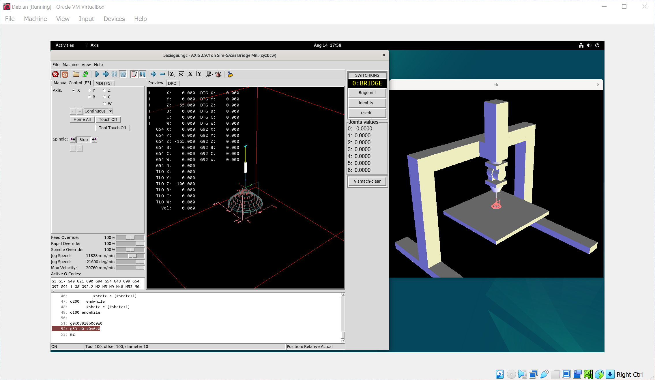
How to add user kinematics for 5 axis bridge mill?

Category: General LinuxCNC Questions

Bridgemill is a somewhat dated example and does not use the 'userkins.comp' template.
For a recent example of tool side rotation kinematic and a more powerful tool-kinematic model see:
github.com/Sigma1912/LinuxCNC_Demo_Confi...ndle-rotary-nutating

To test copy the linked folder into your 'configs' folder and follow the instructions in the 'README' files.

There is also full documentation in html format as well as the Jupyther notebook files on how to derive the two kinematics included.

[edit]
The above examples use 3 kinematic models:
1. Trivial
2. ToolCenterPoint
3. ToolCoordinate

Note that if you set the 'nutation' angle to 90° you have the same kinematics as in the 'bridgemill' sim config.

The above also includes an implementation of the TiltedWorkPlane feature (ie Gcodes G68.x and related) as a python remap.
  • winyk
  • winyk
14 Aug 2024 11:01

How to add user kinematics for 5 axis bridge mill?

Category: General LinuxCNC Questions

Hello, I am a beginner trying to learn LinuxCNC. Recently, I have asked a question about custom kinematics here . With helps from Aciera, I managed to make my first (and very simple) custom kinematics model. Now, want to learn about a more complicated feature in LinuxCNC: the switchable kinematics. So, I started this new topic hoping that someone will me get started with this. I would like to point here that not only that I am new to LinuxCNC, but I am also new to CNC as well, so please bear with me if I ask dumb questions. 

Right now, I want to implement a user kinematics model for the 5axis.ini (located at /linuxcnc-2.9.1/configs/sim/axis/vismach/5axis/bridgemill
/). What I understand from the doc page on switchable kinematics  is that for any configuration, there can be up to 3 kinematics model, where type 0, 1, and 2 typically correspond to default, identity, and user-defined kinematics, respectively. Also, what I learn from the doc is that I can switch between kinematics models using these funny M codes: M428, M429, and M430.
 
I have found 5axis.ini to be a good place to experiment with because the configuration already comes with the three remapped M codes (I have no idea how to add them myself.) I have also played with the configuration a bit in AXIS, switching between default and kinematics type. From what I observed, type 0 is TCP kinematics, type 1 is the identity kinematics, and type 2 is also identity (Presumably it is not yet defined.) The problem is I don't know where the user kinematics definition is located for 5axis.ini. Peaking into the configuration file only lead me to 5axiskins.c, which I believe does not contain any information about the user kinematics.

From the User kinematics provisions section in the doc, it seems that I have to copy src/emc/kinematics/userkfuncs.c to some directory and use it as a template for my user kinematics, however, I am not sure how to do that. Can anybody give me a step-by-step walkthrough on how can I achieve this? Thank you very much.

 
  • nmsk
  • nmsk's Avatar
14 Aug 2024 10:06 - 15 Aug 2024 11:24

Can't set it to OP when configPdos is true

Category: EtherCAT

Hello, I've had this issue for a while now and I haven't found a proper solution for it, when my drives boot up first I need to configure the pdo mapping, I've done this first in Twincat 3 and I copied it to my xml file. When configpdos is true I get this error while it's trying to go to OP:
13726.682821] EtherCAT ERROR 0-0: Failed to set SAFEOP state, slave refused state change (PREOP + ERROR).
[13726.684821] EtherCAT ERROR 0-0: AL status message 0x001E: "Invalid input configuration".

I've found a workaround to this by first launching linuxcnc with configpdos as false,i get an error saying that it can't find the pdo then disconnecting the ethernet cable and connecting it again and then launching linuxcnc again, this always works and keeps the mapping I did at the beginning.
I'm currently using a script like this but while it works it doesn't feel right
/usr/bin/linuxcnc '/home/***/linuxcnc/configs/***/******.ini' #execute the ini for linuxcnc

sleep 10

sudo ip link set eno1 down

sleep 5

sudo ip link set eno1 up

sleep 5

/usr/bin/linuxcnc '/home/***/linuxcnc/configs/***/******.ini' #execute the ini for linuxcnc


Is there a way to do this automatically, or maybe there's an issue I've overlooked.
  • winyk
  • winyk
14 Aug 2024 10:03

How can I modify trivkins.c? (and also other kinematics files)

Category: General LinuxCNC Questions

Thank you. Although I am not sure what is the difference between 'machine movement' and 'axes position' that you have mentioned, I presume that AXIS preview does not reflect the underlying kinematics of the machine, correct? I think the fact that AXIS preview works this way can cause a lot of confusion to newbies like me. If this is the case, then what do the red, green, blue directional vectors shown in the AXIS preview tell us? Is there any way to configure AXIS preview so that the directional vectors agree with the underlying kinematics?

Anyway, after experimenting with 3axis-tutorial.ini, I can now see the effect of reversing the X coordinate in vismach. It turns out that reversing the coordinate in inverse kinematics alone is enough to see this effect, no need to modify the forward kinematics part. I also try with Y and Z as well. Reversing Y works as expected. However, as I try to reverse Z, I encountered error messages telling me that linear move would exceed joint 2's positive limit (no matter I move to +z or -z), and I am not sure why.
 
int kinematicsInverse(const EmcPose * pos,
                      double *j,
                      const KINEMATICS_INVERSE_FLAGS * iflags,
                      KINEMATICS_FORWARD_FLAGS * fflags)
{
    is_ready = 1; // Inverse is not called until homed for KINEMATICS_BOTH

    // Update the kinematic joints specified by the
    // [KINS]JOINTS setting (3 required for this template).
    // Maximum number of joints is defined in include file:
    //         emcmotcfg:EMCMOT_MAX_JOINTS (typ 16)
    // Some joints may be claimed as 'extrajoints' and
    // do not participate in kinematics calculations --
    // $ man motion for more info
    j[0] = pos->tran.x; // joint 0
    j[1] = pos->tran.y; // joint 1
    j[2] = - pos->tran.z; // joint 2

    //example hal pin update (homing reqd before kinematicsInverse)
    *haldata->out = *haldata->in; //dereference
    //read from param example: *haldata->out = haldata->param_rw;

    return 0;
} // kinematicsInverse()

 
Displaying 23911 - 23925 out of 24447 results.
Time to create page: 0.504 seconds
Powered by Kunena Forum