Looks like you guys have been busy, this is awesome.
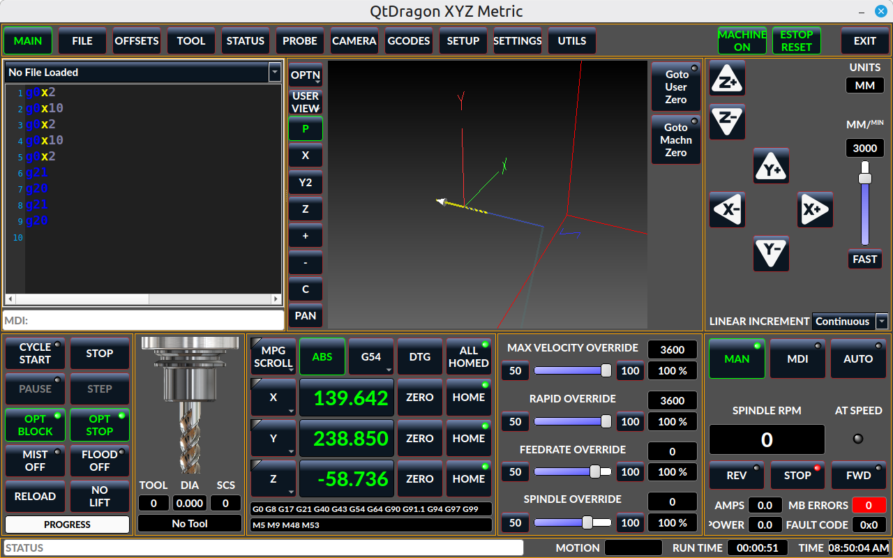
I decided to test out the capabilities of GPT 5.6 Sol by making an entire jerk-limited CNC controller from scratch over the last few weeks. It's mostly done and works, but I'm sure there are still bugs and things I need to finish. I have it working with my mesa 7i96, but haven't connected it all back up to my router yet. It "supports" 6 axes, but I have not even started to worry about the ABC axes yet as I have none on my router.
github.com/a-downing/ngc.
The jerk-limited path solver is a small part of it and I ended up separating it out into its own repo here:
github.com/a-downing/PathTempo. It basically takes in a series of path pieces represented by a curve length and an array of samples of three derivatives (tangent, curvature, curvature-derivative) along that curve for the solver to use. The output is a sequence of time domain cubic polynomials representing cumulative distance along the path, with each polynomial belonging to one path piece. It has helpers to convert lines, arcs, helical arcs, and b-splines into path pieces with their curvature samples.
It has two modes, zero and optimized. In zero mode the acceleration between each path piece is zero, and in optimized mode it can be non-zero for a more time optimal trajectory. The zero mode is very fast (about 0.15% of trajectory time), and optimized mode has taken at most about 1.5% of the time of the trajectories that I've tested so far.
The trajectory planner supplies the real-time backend with timed axis-space polynomial execution spans, quintic for normal continuous motion and cubic for exact stop motion and stop-tails. Each motion chunk includes a proven stop-tail so the backend can stop safely if it reaches the chunk’s branch point without a valid continuation. Homing and probing is done in the backend. Feed hold is done in the backend and only enforces the feed-hold specific tangential jerk limit, and the tangential/normal path acceleration limit. I have not implemented feed override yet, this can be done entirely in the backend if you only allow lowering the feed rate, but for raising it you need to implement it in the planner, and the latency can be up to one planning horizon plus whatever motion the backend has buffered. To have an acceptably low latency the planner would have to only publish a certain amount of motion (measured in time) to the backend. This is doable, but it increases the chance that the backend has to take a stop-tail if something unexpectedly makes planning take longer.
G64 path smoothing is what needs the most work. The time-optimality is more sensitive to the path geometry than anything else by a large margin. A path that to the eye looks extremely smooth can have large curvature derivatives that harshly limit the maximum velocity through them to meet the jerk limit. What I'm basically doing is for lines and arcs above a certain size I join them with a curvature continuous cubic b-spline (not taking full advantage of the G64 P value yet). For spans of arcs/lines that are "small", control points of a quintic b-spline are dropped on their center points and the ends are joined to the enclosing "large" lines/arcs with curvature continuity. If you only do this it will look very smooth, but have large curvature derivatives that severely limit the max velocity. You have you run the spline through a smoothing algorithm that balances minimizing curvature and curvature derivative, while staying within the G64 P value from the original entities. It's already doing this, but I think it could be improved. It should also probably be removing control points in most cases, which it is not.
The one thing I've had no problem with yet is performance. The planner is able to produce work for the backend much, much faster than the backend can consume it. I think it is mostly because GPT 5.6 was able to come up with a very efficient jerk limiting solver, and that the work is pipelined with multiple threads. The first thread evaluates the gcode and produces path geometry and publishes it to a lock free queue, this work only has to be done once, but it takes the most time. Mostly because of the spline smoothing. The trajectory planner reads from this queue and plans a window that includes a stop-tail. Because of the stop-tail some of the same geometry is involved in the next planning window. The planner then publishes the axis space time domain polynomials to another lock free queue in the real-time backend.
I'm not sure if you guys will find any of this useful for the jerk-limiting in LinuxCNC, but I figured I'd drop this here.


") I was a dolt and didn't even realize that the "Normal Cut" button in the GUI toggles "Pierce Only"! I was stuck on trying to use the M3 $2 S1 code but this works just fine.
I was a dolt and didn't even realize that the "Normal Cut" button in the GUI toggles "Pierce Only"! I was stuck on trying to use the M3 $2 S1 code but this works just fine.