Advanced Search

Search Results (Searched for: )

  • Didi
  • Didi
21 Apr 2025 07:42
Proxxon CU4 was created by Didi

Proxxon CU4

Category: General LinuxCNC Questions

Hi,

I'm a newbie on this forum.
Is LinuxCNC compatible with the Proxxon CU4 interface (via parallel port or otherwise)?
  • dctrytsman
  • dctrytsman
21 Apr 2025 06:47
Lathe with C axis was created by dctrytsman

Lathe with C axis

Category: General LinuxCNC Questions

I decided to make a separate post for this. I have a Mazak Qt20 that is retrofitted with Linuxcnc. Currently I have a x and z axis.I want to mount a live spindle to the turret and use the spindle as the C axis. This spindle drive is a A06b-6044-h011 AC servo drive, I'm not sure what motor it uses, there is no tag on it. The motor drives a gearbox that drives the spindle and the spindle is connected to an encoder that is driven with a toothed belt. The encoder is a Tamagawa RFH1024-22-1m.
How should I connect the components ? Do I need to connect the encoder to the drive, as it currently is, or should I connect it directly to the Mesa card? Is there any other I/O pins that I should connect to or from the drive, other than enable, gnd, -V, 0V? How do I set this up in my INI and Hal configurations? 

I will attach a wiring diagram of the drive. 
  • spumco
  • spumco
21 Apr 2025 04:29

After homing X and Y, can I auto move to a non 0,0 location?

Category: General LinuxCNC Questions

Switches shared on one input isn't the issue.

I'm trying to determine where the switches are in relation to the table movement so we can make sure that everything moves the correct direction during homing, and if need be move back to a position you want after homing is complete.
  • ffffrf
  • ffffrf
21 Apr 2025 04:13 - 21 Apr 2025 04:20

XZC live tool sherline lathe Post processor: Not reorienting after a step-down

Category: Fusion 360

This is a long shot but I have been working on a live tool system for my sherline lathe. I am using a tryally QCTP and created a mount for a 33mm 60krpm spindle that I manually control. I modified a hass millturn lathe to output XZC moves only, and modified to use startcode that work with linuxcnc. However, I am noticing an interesting behavior that I am wondering if it is even fixable - it must be, no?The problem: Let';s say I have the endmill parallel to the Z axis, meaning it is in line with the axis of the part (the C axis), and I create a tool path that mills out a wobbly shape out of bar stock, but I need to do it in multiple stepdowns. The post and linuxcnc work as expected for the first stepdown, however, when moving to the next stepdown, it does not reorient itself back to C0, instead it simply continues to mill out the shape exactly where it left off. This means that the second stepped down wobbly shape is some random angle ROTATED from the top (first stepdown) portion. This obviously is not feasible for making parts...However, I am struggling to figure out a solution. One possibility is to try to introduce logic into the post processor that can try and detect when Z distance changes some value and somehow force a reset back to C0 to restart the second stepdown exactly where it needs to, but this seems complex especially if I am going to be varying stepdowns depending on what material I use, what endmill I use, etc.Has anyone thought something like this through? I will upload my Gcode for you all to see. The first stepdown is Z=-6, and the second stepdown starts at Z-10.  

Edit: I added the base Haas post processor that I am using. I almost wonder - shouldnt the post processor have some way of handling this itself? I cant imagine I am the only one trying to do such a cutting move? 
  • RushA
  • RushA
21 Apr 2025 00:55

A simple question: How to use EXPORT_SYMBOL()

Category: General LinuxCNC Questions

hi, thanks!
yes, it's C. I did include A.h in B.c, but it doesn't work.
  • pgf
  • pgf
21 Apr 2025 00:53

After homing X and Y, can I auto move to a non 0,0 location?

Category: General LinuxCNC Questions

@spumco may be onto something? My limit switches are shared: both switches on one circuit. Maybe that's the problem?

@rodw -- My impression and hope was that if I homed to the upper right, I could somehow let the mill know that that point was 12,12 , and that therefore both axes would, yes, count in the negative direction, but not actually ever be negative. They would still go from 0 to 12, but it wouldn't be the 0,0 corner that homing was finding.
Does that make sense?
  • machinedude
  • machinedude's Avatar
21 Apr 2025 00:00
Replied by machinedude on topic Black Friday Deal got me :)

Black Friday Deal got me :)

Category: Plasma & Laser

another update
  • rodw
  • rodw's Avatar
20 Apr 2025 22:04

Are the program's extents available to the g-code?

Category: General LinuxCNC Questions

 Given that the length of the bit is variable, there is no single actual lower hardware limit. It depends on how far the bit protrudes from the collet. Given that, what's the use of the limit? When would it do me any good?

Adding an upper Z limit switch is usually pretty easy and makes it easy to use Linuxcnc as intended. eg Work in G54 offsets.
Normally, you would jog down so the tool touches the workpiece and set your g54 offset. 
Using work coordinates eg G54 was my biggest learning.
  • rodw
  • rodw's Avatar
20 Apr 2025 21:49

After homing X and Y, can I auto move to a non 0,0 location?

Category: General LinuxCNC Questions

You have to remember you are dealing with cartesian coordinates.
You can home to any corner you wish. Homing to the lower left of the worktable means all x,y coordinates are in the positive quadrant.
Homing to another corner will mean at least one axis will count in the negative direction. Think of the graphs you drew at school

I did have a machine where the home switch was at max Y but I added a home offset to make the home position at min Y
Thinking about it after using it, I realized I could have homed it at the home switch position so the Y axis would count in the negative direction beecause once you zero G54 offsets at lower left on your workpiece, everything would count in a positive direction anyway.
  • rodw
  • rodw's Avatar
20 Apr 2025 21:36
Replied by rodw on topic Should I switch from AXIS to QtDragon?

Should I switch from AXIS to QtDragon?

Category: Qtvcp

I have plenty, you are welcomed to use them, but i can not guarantee the quality! They do chew on everything in the shop though, seem pretty healthy by the looks and the speed they move through the shop. 

I had one but I bought a better mousetrap and the offending rodent was dispatched in under an hour!
Anybody want a used but battle proven mousetrap I no longer have a use for?
  • spumco
  • spumco
20 Apr 2025 21:14

After homing X and Y, can I auto move to a non 0,0 location?

Category: General LinuxCNC Questions

Just to be sure about this...where are the limit switches physically located in relation to the travels?

With the table all the way back and to the right?
  • spumco
  • spumco
20 Apr 2025 21:03

Determining Angular Scale - Help w/ Microsteps

Category: Configuration Tools

[Sorry for the following Wall-O-Text, but I got on a roll ]

OP-
Incremental encoders have a resolution which can be expressed either as 'lines' or 'counts'.

In the case of a wheel with slots, each opening is considered a line.  For optical glass encoders, a line is one of the etched or printed black lines on the encoder disc.

If you have a 1000-line (or 1000-count) encoder, that means the disc has 1000 of these interruptions in the optical sensor/reader.

What causes things to get a little confusing is that the drive doesn't just sense one pulse for each line that passes the optical sensor.

There are two sensors in the read head, and one is slightly advanced from the other.  Both of these sensors send signals to the drive, and we call them the "A" and "B" pulses.  So that's two pulses per physical line on the encoder disc.

But it gets better... the drive can sense the rising edge of each electical pulse, as well as the falling edge.  For example, when a line goes past the A-sensor the drive sees a voltage change from 0 to 5v.  Then when the line gets all the way past the sensor the drive sees a transition from 5 to 0v.  Each transition - 0-5 and 5-0 - counts as a 'pulse' to the drive.

Same thing is happening on the B-sensor, and since the A-sensor is advanced a little bit from the B-sensor, the drive can count 4 pulses for each encoder line.  So we basically get a 4x improvement on encoder resolution for free.

Since your motor has a 1000-line encoder, the drive expects to count 4000 pulses per revolution.  This where the "1000/4000" jargon I dropped on you earlier comes from.

www.motioncontroltips.com/faq-what-do-x1...ncremental-encoders/

You can imagine what happens if the drive is programmed to expect 4000 pulses per rev, but the encoder is a 800-line (or some other non-matching value).  The drive thinks the motor is spinning at a different RPM than reality, and the motor magnetic poles don't line up with what the drive has calculated should be the case.  The drive won't turn on/off the coils at the right time, and the motor might turn but would make noise and not move to the correct position.  A significant mismatch would probably result in the drive erroring out.

That's why I suggested checking what value the drive was programmed.  It was unlikely there was a mismatch as most of (if not all) these cheap closed-loop steppers have 1000-line encoders so the drives are generally programmed for 4000 pulses, but it doesn't hurt to check while you're in the tuning software anyway.

You do NOT adjust the 4000-pulse encoder setting in the drive, regardless of the INPUT steps-per-rev setting in the drive (or in LCNC).  That encoder number is explicitly determined by the encoder on the motor.

Input steps per revolution on a programmable drive can be just about any arbirtary number.  While the motor has 200 physical steps (positions) due to it's construction, you can program the drive to move however far you want per input pulse (not encoder pulses).  If you program 1ppr input, then the motor will turn one full revolution for each pulse.  If you program the drive to 3157ppr, it will move 1/3157 of a rotation per input pulse.

Setting the drive to a higher input ppr than the encoder pulses means the drive is just guessing - the encoder resolution has to be higher than the input pulse setting for everything to work cleanly.  You can set the input higher than the encoder in the software, but there's no way the drive can accurately move the motor exactly where you want it because the drive has to guess where the motor is between the encoder pulses.

Older, non-programmable stepper drives were limited to either 200 input steps/rev for a 1.8 degree motor, or some multiple of that native 200 selectable via dip switches.  So when you see '4x', '8x', etc. that means you got to pick 200ppr, 800ppr, 1600ppr and so forth.

If after you take in to account the mechanical transmission (ball screw, belt ratio, etc.) the math didn't work out cleanly, you wind up with some strange number of input steps per machine unit (inches, mm, degrees).  Thats how you get from a drive set to 8x (1600ppr), through a 3:1 belt, and your units are in degrees (1/360)... so you have to tell LCNC to output 13.3333... steps per degree of spindle rotation.

LCNC can't output one third of a step, so whenever you have a non-whole number of steps per unit of measurement, there's a bit of "ish" involved with where the motor lands. LCNC doesn't lose track of where it is, but it can't move the motor exactly where you want.

However... if you program the drive with an input ppr that results in a whole number for each machine unit - degrees in your case - then LCNC can output a number of steps/pulses that can resolve to exactly one degree.  For your belt drive, that means 1200ppr at the drive input results in 10 steps per degree - a nice whole number which means LCNC can resolve to 0.1 degrees per step.  And 2400ppr gives you 0.05 degree per input step resolution.

Remember a few paragraphs ago when I mentioned keeping the input ppr lower than the encoder resolution?  Both 1200 and 2400ppr input values are lower than the 4000 pulse encoder, which means the drive would still have a chance of positioning the motor fairly accurately.

You machine isn't going to actually be 0.05 degree accurate due to variations in the belt, pulleys, friction, lost step here or there... but your INI file will certainly look neater.

Hope that helps.
  • cmorley
  • cmorley
20 Apr 2025 20:42

QtDragon_hd + Basic Probe - probing results not displayed

Category: Qtvcp

I see you are missing the abort INI entry:
linuxcnc.org/docs/stable/html/gui/qtdrag...tml#_abort_detection
This is how the probing routines detect errors.
Please add it and the file it requires and try the probing again.
  • 3404gerber
  • 3404gerber
20 Apr 2025 20:13
Replied by 3404gerber on topic Configuring 6 axis robot arm with lcnc

Configuring 6 axis robot arm with lcnc

Category: HAL

Hi,

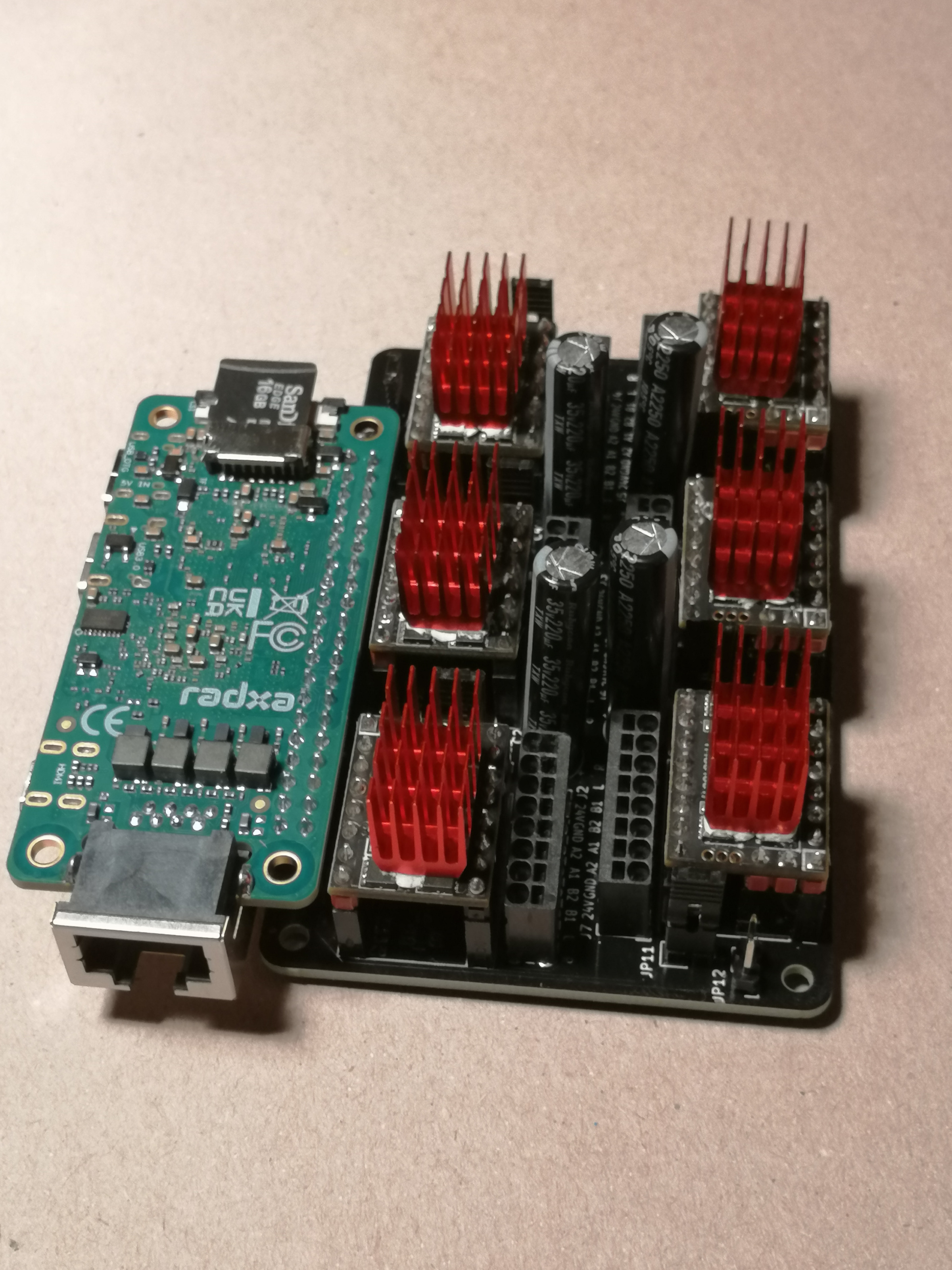
I'm currently playing with TMC5160 on Linuxcnc in full SPI mode and am happy with the result. Just received a pcb to stack 6 of them on a Pi Hat: (well, on a Radxa zero 3E on the picture)


You only use 5 pins from the PI, so plenty left for other stuff. I also added the possibility to connect two 24V end switches directly on the TMC's. And a clock signal generator is on the pcb, so the TMC's share a 16MHz clock, which means better sync and faster SPI communication.
  • langdons
  • langdons
20 Apr 2025 19:45
Replied by langdons on topic Should I switch from AXIS to QtDragon?

Should I switch from AXIS to QtDragon?

Category: Qtvcp

Enough jokes about mice!

I will copy the config and try QtDragon.
Displaying 6466 - 6480 out of 24042 results.
Time to create page: 0.303 seconds
Powered by Kunena Forum