Search Results (Searched for: )
- timo
- timo
29 Apr 2026 14:22
- denhen89

29 Apr 2026 13:47
- grandixximo

29 Apr 2026 12:46
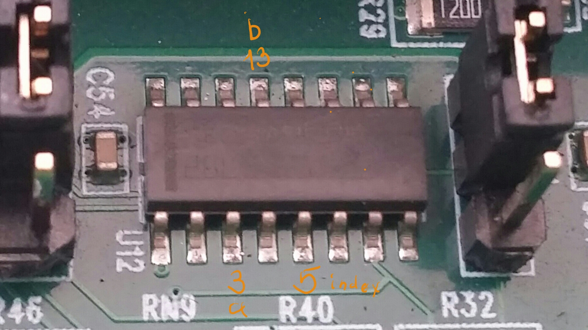
Replied by grandixximo on topic Ethercat - assinged the same pdos to multiple Slave-Signals?
Ethercat - assinged the same pdos to multiple Slave-Signals?
Category: EtherCAT
- timo
- timo
29 Apr 2026 12:23
Replied by timo on topic Ich brauche Hilfe bei meinem Getriebe
Ich brauche Hilfe bei meinem Getriebe
Category: HAL
- timo
- timo
29 Apr 2026 12:15
Replied by timo on topic Ich brauche Hilfe bei meinem Getriebe
Ich brauche Hilfe bei meinem Getriebe
Category: HAL
")
- nighteagle
- nighteagle
29 Apr 2026 12:05 - 29 Apr 2026 12:20
Lathe=TRUE and after TouchOff z-Axis i can not move Z-Axis was created by nighteagle
Lathe=TRUE and after TouchOff z-Axis i can not move Z-Axis
Category: General LinuxCNC Questions
- spumco
- spumco
29 Apr 2026 11:43
- mgiaco
- mgiaco
29 Apr 2026 10:48 - 29 Apr 2026 10:51
Mesa 7i76e pncconf open loop stepper leadshine was created by mgiaco
Mesa 7i76e pncconf open loop stepper leadshine
Category: HAL
- MiMaMoadlo
- MiMaMoadlo
29 Apr 2026 10:48
Replied by MiMaMoadlo on topic No unhoming after emergency-stop or limit-sw trigger
No unhoming after emergency-stop or limit-sw trigger
Category: General LinuxCNC Questions
- grandixximo
29 Apr 2026 10:01
Replied by grandixximo on topic How to fix "Queue is not empty after probing"
How to fix "Queue is not empty after probing"
Category: General LinuxCNC Questions
- abs32
- abs32
29 Apr 2026 08:14 - 29 Apr 2026 08:16
Replied by abs32 on topic How to fix "Queue is not empty after probing"
How to fix "Queue is not empty after probing"
Category: General LinuxCNC Questions
- Surmetall

29 Apr 2026 07:34
Replied by Surmetall on topic LinuxCNC and Beckhoff AX5000 servo drives
LinuxCNC and Beckhoff AX5000 servo drives
Category: EtherCAT
- xenon-alien

29 Apr 2026 07:33
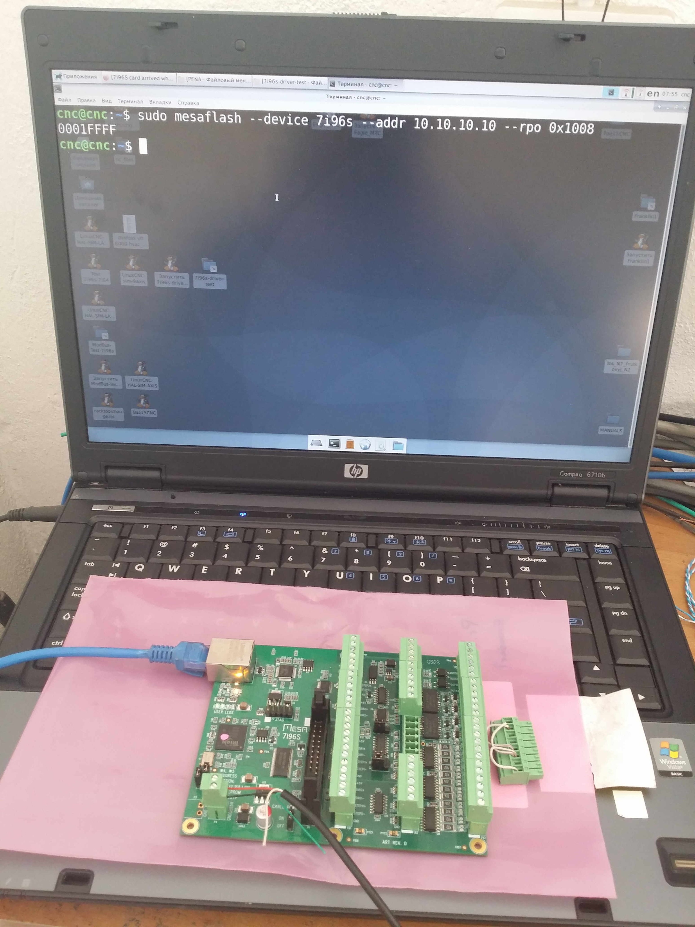
Replied by xenon-alien on topic 7i96S card arrived what setup is recomended
7i96S card arrived what setup is recomended
Category: Driver Boards
- tommylight

29 Apr 2026 05:06
Replied by tommylight on topic 7i96S card arrived what setup is recomended
7i96S card arrived what setup is recomended
Category: Driver Boards
- xenon-alien
29 Apr 2026 05:01
Replied by xenon-alien on topic 7i96S card arrived what setup is recomended
7i96S card arrived what setup is recomended
Category: Driver Boards
Time to create page: 0.552 seconds