Search Results (Searched for: )
- WKS-3D

03 Aug 2025 10:18
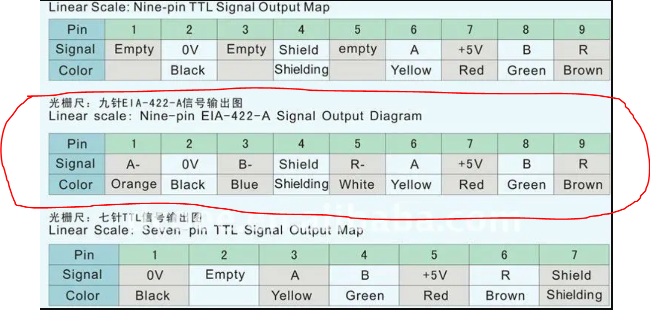
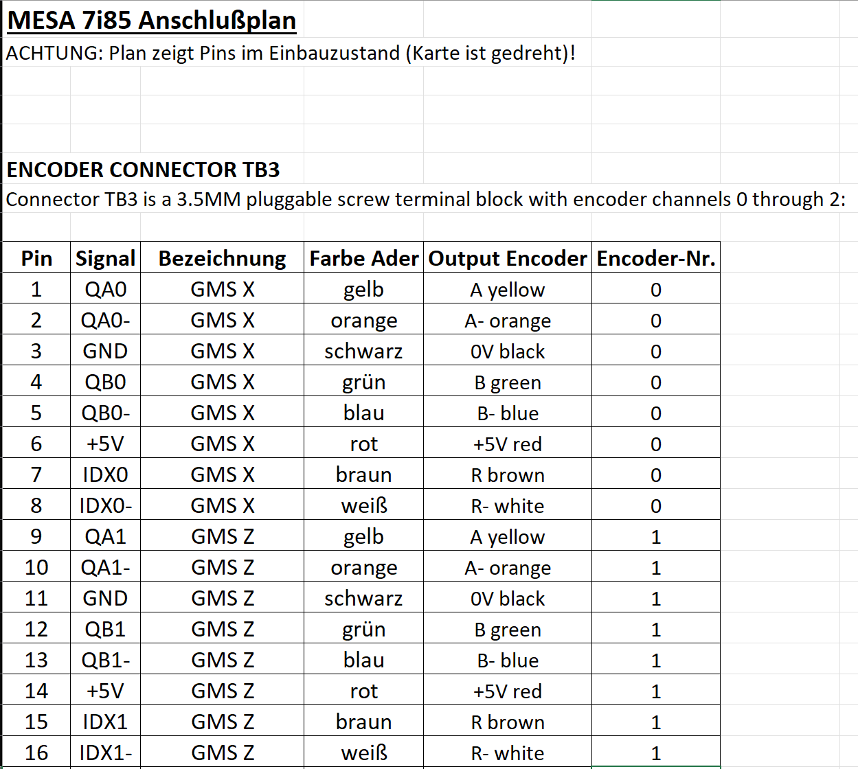
Replied by WKS-3D on topic Glasmaßstab EIA-422 an Mesa 7i85 (S)
Glasmaßstab EIA-422 an Mesa 7i85 (S)
Category: Deutsch
- pkludwig

03 Aug 2025 10:12
Replied by pkludwig on topic Simulating a hm2_eth driver (e.g. mesacard 7i76e)
Simulating a hm2_eth driver (e.g. mesacard 7i76e)
Category: Driver Boards
Time to create page: 0.597 seconds