Advanced Search

Search Results (Searched for: )

  • JT
  • JT's Avatar
11 Apr 2025 13:15
Replied by JT on topic Flexible GUI

Flexible GUI

Category: Other User Interfaces

  • Fianna
  • Fianna's Avatar
11 Apr 2025 13:14 - 11 Apr 2025 15:58
VHD Header Help was created by Fianna

VHD Header Help

Category: Driver Boards

Hi All

My intent is to merge some vhd files to get a 7i76e + 7i78 + 7i89 

I saw a post here (from PCW I believe) sayign the count in the 4th column was the number of those modules, so for the stepgens I want (6x or more) I've been putting x06, and same for the encoders (1x spindle + 6x on the DB25 headers), just increasing the built in Qcount. I believe I don't need muxed ones (I have single ended A/B/Z glass scales), finally I then make sure the total number of entries in the whole array was the same as the standard hostmot2 7i76e examples. No ide if this logic is sound or not... 

(HM2DPLLTag,x"00",ClockLowTag, x"01",HM2DPLLBaseRateAddr&PadT,HM2DPLLNumRegs,x"00",HM2DPLLMPBitMask), (WatchDogTag,x"00",ClockLowTag, x"01",WatchDogTimeAddr&PadT, WatchDogNumRegs,x"00",WatchDogMPBitMask),
(IOPortTag,x"00",ClockLowTag, x"03",PortAddr&PadT,IOPortNumRegs,x"00",IOPortMPBitMask),
(QcountTa    x"02",   ClockLowTag,x"06",QcounterAddr&PadT,QCounterNumRegs,x"00",QCounterMPBitMask),  
(StepGenTag,x"02",ClockLowTag, x"06", StepGenRateAddr&PadT,StepGenNumRegs,x"00",StepGenMPBitMask)
(MuxedQcountTag, MQCRev,ClockLowTag, x"01",MuxedQcounterAddr&PadT,MuxedQCounterNumRegs,x"00", MuxedQCounterMPBitMask),
(MuxedQCountSelTag, x"00",ClockLowTag, x"01", NullAddr&PadT,x"00",x"00",x"00000000"),
(SSerialTag,x"00",ClockLowTag,x"01",SSerialCommandAddr&PadT,SSerialNumRegs,x"10",SSerialMPBitMask),  
(LEDTag,x"00",ClockLowTag,x"01",LEDAddr&PadT,LEDNumRegs,x"00",LEDMPBitMask),
(NullTag,x"00",NullTag,x"00",NullAddr&PadT,x"00",x"00",x"00000000"),
(NullTag, x"00", NullTag,x"00",NullAddr&PadT,x"00",    
more null
more null

until I get to the same line number as the examples so same number of modules. 

I think I've made a dud bit file and written it to my 7i76e at some stage, the first time I tried to write it, mesaflash did the erasing, got halfway through the writing "WWWW..." thing and the terminal just hung. Ctrl + C'd the terminal, and I think the 7i76e stopped responding. 
I power cycled the card itself, and now mesaflash can see it and write known good bit files to it, but after I write new bit files and --reload, the --readhmid just returned "None" for all of the channels. 
I've since power cycled a few times and it seems to be writing standard bitfiles again by some miracle.

Can someone explain the header logic or point me to an explanation? 
Can I just keep changing the module count freely and the Xilinx tool will flag if it runs out of space? 
If the Xilinx tool compiles it okay can I be confident it won't brick the board?
How do I know if it's in fallback or normal boot? 
What do the other columns in the header do, do I need to set memory addresses where the modules start or block sizes or anything? I'm wondering if I could be increasing module count and then overflowing the following module or something. 
Does the total number of modules in that array need to be correct / a specific number / does it matter? 

I've skimmed the hostmot2 dataflow vhd file but fallen at the first hurdle: 


-- decodes -- --    IDROM related signals
-- Extract the number of modules of each type from the ModuleID
constant StepGens: integer := NumberOfModules(TheModuleID,StepGenTag);


This line obviously reads that count but I can't see where NumberOfModules (function? attribute of the an object called "work"?) is defined so I'm lost. As you can tell I don't have a clue how this code works so I'm just a smidge lost :) 
I've had PCW post a few bitfiles here for me, for which I'm eternally grateful, but I feel bad so I'd prefer to acutally understand what's going on and be able to do it myself (and pass the favour on if it's not potentially harmful to someone elses setup!)

Thanks, 
Kealan
  • JT
  • JT's Avatar
11 Apr 2025 13:12
Replied by JT on topic Flexible GUI

Flexible GUI

Category: Other User Interfaces

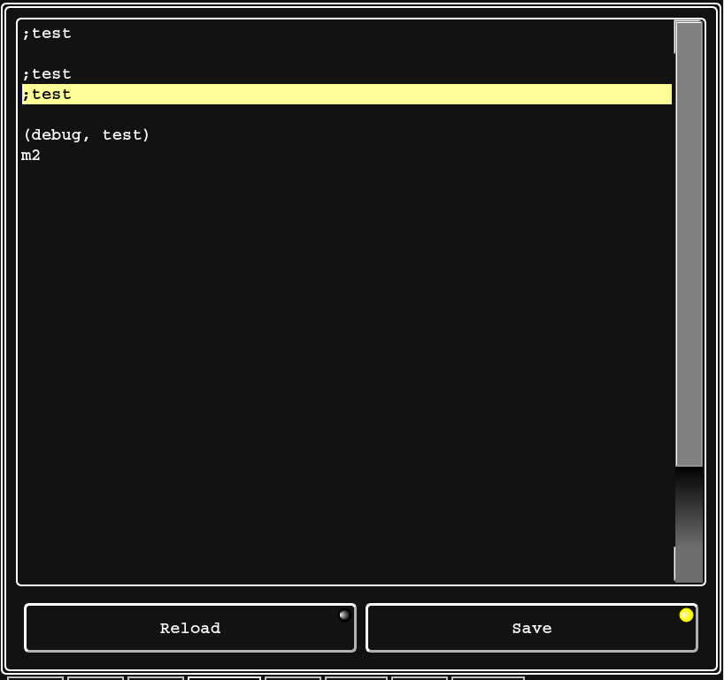
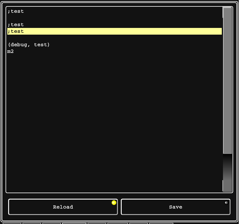
I even added LED's to the reload and save button if you want them you just have to add a Dynamic Property. Big thanks to Chris for helping me understand the LED's

Just edited the nc code file.


Just saved the file so it shows a reload is needed.


So much fun...
JT
  • andypugh
  • andypugh's Avatar
11 Apr 2025 13:07
Replied by andypugh on topic ENCODER_RATIO function implementation.

ENCODER_RATIO function implementation.

Category: General LinuxCNC Questions

The whole thing has evolved over time, and I have failed to update the wiki page. (its been about 13 years...)

I have attached the whole config folder.  But be aware that this machine has many configurations and so has several INI files. 
If you start with the hobbing.ini and look to see which HAL files it uses, you should be able to identify all the used files. 
  • andypugh
  • andypugh's Avatar
11 Apr 2025 12:59
Replied by andypugh on topic Strange behaviour of custom component

Strange behaviour of custom component

Category: Advanced Configuration

I think we need to see the code.
  • Aciera
  • Aciera's Avatar
11 Apr 2025 12:44

Planning to Retrofit a Mazak Integrex200Y Mill-Turn Machine

Category: Advanced Configuration

The easiest way to find out if your kinematic is gibberish is to try to compile and install it using 'halcompile'. Verifying the kinematic model is of course more difficult and usually requires either a vismach model of the machine or the machine itself.
  • JT
  • JT's Avatar
11 Apr 2025 11:04
Replied by JT on topic Flexible GUI

Flexible GUI

Category: Other User Interfaces

Any chance of adding a "save" button for the code viewer? I see the "save_as_pb", I'd rather just overwrite the existing file without a prompt if it's possible.
 

I never thought about that but it makes sense because you can edit the nc file in Flex you should be able to save your edits then reload.

Save menu item and button added.

JT
  • jochen91
  • jochen91
11 Apr 2025 10:25 - 11 Apr 2025 10:34

Planning to Retrofit a Mazak Integrex200Y Mill-Turn Machine

Category: Advanced Configuration

I've played around with ChatGPT and got at least in my limited knowledge a usefull locking Kinematics file out of it.I used the millturn example and added switchable TCP functionality from the 5Axis demo. I still did not add die virtual Y axis. I would be realy thankfull if somebody could provide feedback if the supplied code is not 100% gibberish.

Since i'm still in the phase of feasibility study i dont have many great pictures of the machine. I live roughly 3hours away from it. If everything goes well, i hope i can post pictures in the upcoming months (if I'm lucky weeks). But here at least is a picture of the 40 Tool KM63 ATC. Best i can do so far ;)

#include "rtapi_math.h"
#include "kinematics.h"

static struct haldata {
    // Declare hal pin pointers used for xyzcb_tdr kinematics:
    hal_float_t *tool_offset_z;
    hal_float_t *x_offset;
    hal_float_t *z_offset;
    hal_float_t *x_rot_point;
    hal_float_t *y_rot_point;
    hal_float_t *z_rot_point;

    //Declare hal pin pointers used for switchable kinematics
    hal_bit_t   *kinstype_is_0;
    hal_bit_t   *kinstype_is_1;
    hal_bit_t   *kinstype_is_2;
} *haldata;

static int xyzcb_millturn_setup(void) {
#define HAL_PREFIX "xyzcb_millturn"
    int res = 0;
    // inherit comp_id from rtapi_main()
    if (comp_id < 0) goto error;
    // set unready to allow creation of pins
    if (hal_set_unready(comp_id)) goto error;

    haldata = hal_malloc(sizeof(struct haldata));
    if (!haldata) goto error;

    // hal pins required for xyzcb_millturn kinematics:
    res += hal_pin_float_newf(HAL_IN, &;(haldata->tool_offset_z), comp_id, "%s.tool-offset-z", HAL_PREFIX);
    res += hal_pin_float_newf(HAL_IN, &;(haldata->x_offset), comp_id, "%s.x-offset", HAL_PREFIX);
    res += hal_pin_float_newf(HAL_IN, &;(haldata->z_offset), comp_id, "%s.z-offset", HAL_PREFIX);
    res += hal_pin_float_newf(HAL_IN, &haldata->x_rot_point, comp_id, "%s.x-rot-point", HAL_PREFIX);
    res += hal_pin_float_newf(HAL_IN, &haldata->y_rot_point, comp_id, "%s.y-rot-point", HAL_PREFIX);
    res += hal_pin_float_newf(HAL_IN, &haldata->z_rot_point, comp_id, "%s.z-rot-point", HAL_PREFIX);

    // hal pins required for switchable kinematics:
    res += hal_pin_bit_new("kinstype.is-0", HAL_OUT, &;(haldata->kinstype_is_0), comp_id);
    res += hal_pin_bit_new("kinstype.is-1", HAL_OUT, &;(haldata->kinstype_is_1), comp_id);
    res += hal_pin_bit_new("kinstype.is-2", HAL_OUT, &;(haldata->kinstype_is_2), comp_id);

    // define default kinematics at startup for switchable kinematics
    *haldata->kinstype_is_0 = 1; // default at startup -> Milling Mode without TCP
    *haldata->kinstype_is_1 = 0; // -> Turning Mode
    *haldata->kinstype_is_2 = 0; // -> Milling Mode with TCP

    if (res) goto error;
    hal_ready(comp_id);
    rtapi_print("*** %s setup ok\n", __FILE__);
    return 0;
error:
    rtapi_print("\n!!! %s setup failed res=%d\n\n", __FILE__, res);
    return -1;
#undef HAL_PREFIX
}

EXPORT_SYMBOL(kinematicsType);
EXPORT_SYMBOL(kinematicsSwitchable);
EXPORT_SYMBOL(kinematicsSwitch);
EXPORT_SYMBOL(kinematicsInverse);
EXPORT_SYMBOL(kinematicsForward);

static hal_u32_t switchkins_type;

int kinematicsSwitchable() { return 1; }

int kinematicsSwitch(int new_switchkins_type) {
    switchkins_type = new_switchkins_type;
    rtapi_print("kinematicsSwitch(): type=%d\n", switchkins_type);
    // create case structure for switchable kinematics
    switch (switchkins_type) {
        case 0:
            rtapi_print_msg(RTAPI_MSG_INFO, "kinematicsSwitch:TYPE0\n");
            *haldata->kinstype_is_0 = 1;
            *haldata->kinstype_is_1 = 0;
            *haldata->kinstype_is_2 = 0;
            break;
        case 1:
            rtapi_print_msg(RTAPI_MSG_INFO, "kinematicsSwitch:TYPE1\n");
            *haldata->kinstype_is_0 = 0;
            *haldata->kinstype_is_1 = 1;
            *haldata->kinstype_is_2 = 0;
            break;
        case 2:
            rtapi_print_msg(RTAPI_MSG_INFO, "kinematicsSwitch:TYPE2\n");
            *haldata->kinstype_is_0 = 0;
            *haldata->kinstype_is_1 = 0;
            *haldata->kinstype_is_2 = 1;
            break;
        default:
            rtapi_print_msg(RTAPI_MSG_ERR, "kinematicsSwitch:BAD VALUE <%d>\n", switchkins_type);
            *haldata->kinstype_is_1 = 0;
            *haldata->kinstype_is_0 = 0;
            *haldata->kinstype_is_2 = 0;
            return -1; // FAIL
    }
    return 0; // ok
}

KINEMATICS_TYPE kinematicsType() {
    static bool is_setup = 0;
    if (!is_setup) xyzcb_millturn_setup();
    return KINEMATICS_BOTH; // set as required
}

int kinematicsForward(const double *j, EmcPose *pos, const KINEMATICS_FORWARD_FLAGS *fflags, KINEMATICS_INVERSE_FLAGS *iflags) {
    (void)fflags;
    (void)iflags;
    double x_rot_point = *(haldata->x_rot_point);
    double y_rot_point = *(haldata->y_rot_point);
    double z_rot_point = *(haldata->z_rot_point);

    double dz = *(haldata->z_offset);
    double dt = *(haldata->tool_offset_z);

    double sc = sin(j[3] * TO_RAD); // Replaced A-axis with C-axis
    double cc = cos(j[3] * TO_RAD); // Replaced A-axis with C-axis
    double sb = sin(j[4] * TO_RAD);
    double cb = cos(j[4] * TO_RAD);

    // Define forward kinematic models using case structure for switchable kinematics
    switch (switchkins_type) {
        case 0: // Milling Mode without TCP
            pos->tran.x = j[0];
            pos->tran.y = j[1];
            pos->tran.z = j[2];
            pos->c = j[3]; // Replaced A-axis with C-axis
            pos->b = j[4]; // B-axis
            break;
        case 1: // Turning Mode
            pos->tran.x = j[2];
            pos->tran.y = -j[1]; // Invert Y-axis
            pos->tran.z = j[0];  // Swap X and Z for Turning Mode
            pos->c = j[3]; // C-axis
            pos->b = j[4]; // B-axis
            break;
        case 2: // Milling Mode with TCP
            double px = j[0] - x_rot_point;
            double py = j[1] - y_rot_point;
            double pz = j[2] - z_rot_point - dt;

            pos->tran.x = cb * px + sc * sb * py - cc * sb * pz + cb * dz + sb * dz + x_rot_point;
            pos->tran.y = cc * py + sc * pz + y_rot_point;
            pos->tran.z = sb * px - sc * cc * py + cc * cc * pz + sb * dx + cb * dz + z_rot_point + dt;
            pos->c = j[3]; // C-axis
            pos->b = j[4]; // B-axis
            break;
    }
    pos->u = 0;
    pos->v = 0;
    pos->w = 0;
    return 0;
}

int kinematicsInverse(const EmcPose *pos, double *j, const KINEMATICS_INVERSE_FLAGS *iflags, KINEMATICS_FORWARD_FLAGS *fflags) {
    (void)iflags;
    (void)fflags;
    double x_rot_point = *(haldata->x_rot_point);
    double y_rot_point = *(haldata->y_rot_point);
    double z_rot_point = *(haldata->z_rot_point);

    double dx = *(haldata->x_offset);
    double dz = *(haldata->z_offset);
    double dt = *(haldata->tool_offset_z);

    double sc = sin(pos->c * TO_RAD); // Replaced A-axis with C-axis
    double cc = cos(pos->c * TO_RAD); // Replaced A-axis with C-axis
    double sb = sin(pos->b * TO_RAD);
    double cb = cos(pos->b * TO_RAD);

    double qx = 0;
    double qy = 0;
    double qz = 0;

    switch (switchkins_type) {
        case 0: // Milling Mode without TCP
            j[0] = pos->tran.x;
            j[1] = pos->tran.y;
            j[2] = pos->tran.z;
            j[3] = pos->c; // Add C-axis here
            j[4] = pos->b; // Add B-axis here
            break;
        case 1: // Turning Mode
            j[0] = pos->tran.z;  // Swapping X and Z axes for turning mode
            j[1] = -pos->tran.y; // Negating Y-axis for turning mode
            j[2] = pos->tran.x;  // Swapping X and Z axes for turning mode
            j[3] = pos->c; // Add C-axis here
            j[4] = pos->b; // Add B-axis here
            break;
        case 2: // Milling Mode with TCP
            qx = pos->tran.x - x_rot_point - dx;
            qy = pos->tran.y - y_rot_point;
            qz = pos->tran.z - z_rot_point - dz - dt;

            j[0] = cb * qx + sc * sb * qy - cc * sb * qz + cb * dx - sb * dz + x_rot_point;
            j[1] = cc * qy + sc * qz + y_rot_point;
            j[2] = sb * qx - sc * cc * qy + cc * cc * qz + sb * dx + cb * dz + z_rot_point + dt;
            j[3] = pos->c; // Add C-axis here
            j[4] = pos->b; // Add B-axis here
            break;
    }
    return 0;
}
 
  • vre
  • vre
11 Apr 2025 10:14 - 11 Apr 2025 10:22
Replied by vre on topic Un-lobotomizing a Maho MH600T

Un-lobotomizing a Maho MH600T

Category: CNC Machines

I haven't open thread for my machine.
I have also some small changes to your crowbar interpolator circuit:
added parallel to C2 capacitor 1uF
replaced the diode D3 with 5v6
replaced R2 with lower value i think 270R or 330R
and put soldered fuses 1A.
What changes have you done ?
Is this the updated shematic you have done or not uploaded yet ?
github.com/finngineering/sincos_interpol...master/schematic.pdf
  • PCW
  • PCW's Avatar
11 Apr 2025 02:43
Replied by PCW on topic 2. Spindle how is to do, to get it?

2. Spindle how is to do, to get it?

Category: HAL

Do you have one spindle working?
Can you post you hal/ini files?
  • richcolvin
  • richcolvin's Avatar
11 Apr 2025 00:37
Replied by richcolvin on topic 2. Spindle how is to do, to get it?

2. Spindle how is to do, to get it?

Category: HAL

Did you figure it out? I’m having the same issue
  • tcbmetalworks
  • tcbmetalworks
10 Apr 2025 21:23
Replied by tcbmetalworks on topic 10.5 x 25 cnc plasma table retrofit

10.5 x 25 cnc plasma table retrofit

Category: Computers and Hardware

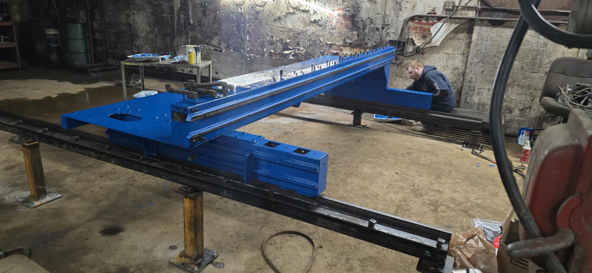
I got the gantry together was alot of work  and planning to make sure it was all straight. It rolls pretty nicely you can feel the hop between rails a little but I think with the size of the machine the vibrations will smooth out. If it appears in the cut quality I will switch to linear rails. We are painting it right now looks like a brand new machine! A friend of mine may have some brushless dc motors hes getting from work for me, we will see otherwise likely going to go with china brand servo motors. Still alot of work ahead of me on this project, im hoping it will be a reliable machine cut around the clock without issues. 

  • PCW
  • PCW's Avatar
10 Apr 2025 19:44
Replied by PCW on topic Is my 7I97T broken?

Is my 7I97T broken?

Category: Driver Boards

That unfortunately  means that the Ethernet chip has been damaged
by large enough ESD that a spark jumped from the RJ45 housing to the
LED pin. This is why it's very important to ground the frame ground
connection, especially when testing and plugging/unplugging cables.

This is repairable by replacing the Ethernet chip.
 
  • Marc_P
  • Marc_P
10 Apr 2025 19:37
Replied by Marc_P on topic Is my 7I97T broken?

Is my 7I97T broken?

Category: Driver Boards

Yes, after the changes I've power cycled the card and also changed die IP address on the host.
With noch ethernet cable connected, the right LED of the RJ45 port light steady yellow.
Displaying 6811 - 6825 out of 24292 results.
Time to create page: 0.663 seconds
Powered by Kunena Forum