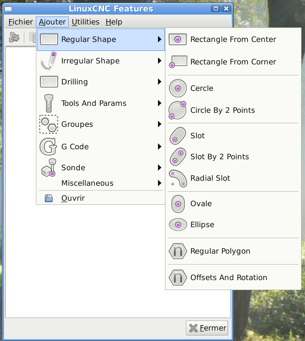
LinuxCNC Features - a kind of NGCGUI
- Nick
-
 Topic Author
- Offline
- Premium Member
-

- Posts: 125
- Thank you received: 11
I believe that Features has a button to Save as - to save the XML file, and after that you can Import it.I agree that saving to XML is a must so we do not have to start over again for the same or very similar job.
Moreover we have done import as a Feature in the Catalog, so you can Import your "Saved as" Subroutine from the catalog the very same way you would add a new feature.
Please Log in or Create an account to join the conversation.
- FernV
-

- Offline
- Platinum Member
-

- Posts: 457
- Thank you received: 124
I have a few more important changes to make before it can be posted. And I also think it should be part or LinuxCNC distribution. It is much better now than NGCGUI and will be even better when I am done
Stay tuned
Regards
Fern
Please Log in or Create an account to join the conversation.
- FernV
-
- Offline
- Platinum Member
-
- Posts: 457
- Thank you received: 124
Congratulations! You have done very good job in structuring folders and all your coding is really clean
I have a few suggestion and comments
- You could enter comments in the header, I mean the line that names the feature and it will be saved, copied. You do not have to add a PARAM_COMMENT. It will save a line on your display and you will see the comment even when it is not expanded
- Having PARAM_ENA is a GREAT idea, no need to delete the feature when not needed. IMHO the label should be "Enable" not "ENA"
- Since copied features now have a different ID, self_id works OK
- If you use linked-line-xy more than once, you will have a bug. Same problem with any feature that the sub is in [DEFINITIONS]. Better use include-once in [DEFINITIONS] like you did in rectangle-cc.ini and circle.ini
- Do you use DRAW? I always had a bug in milldraw.py and it would not start at all. I decided to drop it
- About "Library elements", I modified the code where you can import or add features after the selected one or select "items" and it will be inserted there
- Icons can be easily created, duplicated and modified with Inkscape. You then use create_icons.py. You can set the size of icons and images. Delete the icons you want to replace
- About "My cutting-params.ini (you find it under misc->tool) now holds also the tool diameter", I simply use Change Tools and LinuxCNC takes care of the rest for tool compensation. Am I missing something ?
Your work will be very usefull to many machinists.
I include my menu definitions, so you know how to make yours ready when I post my version in a short time
Best regards
Fern
Please Log in or Create an account to join the conversation.
- turbospeedskater
- Offline
- New Member
-

- Posts: 16
- Thank you received: 0
Hi Nick,
@Nick: Thanks for the hint, I will check out how to use github tonight.
Any hints/suggestions what and how to do?
@Fern: thanks for the suggestions!
I did not find out, that I can enter a comment line in the header.
That makes much more sense than my PARAM_COMMENT.
I will kick it out in the next release.
I agree _ENABLE is much better than _ENA. But during my work on this, I once have had a "line too long" error.
I can not really remember, but I think that error was coming from the G-code interpreter inside LinuxCNC.
That is the reaason why I have renamed all of Nicks global variables from "_global_something" to "_g_something".
And also the reason why my variable names are short "ENA' instead of "ENABLE".
Up to now I have not used lined-line-xy. That is a feature I have only copied and adjusted to my variable names.
Not really tested. But I willl check that.
DRAW is also a thing I never really used up to now.
Icons from Inkscape: Yes, if you know how to use inkscape.... But when I started thinking about this, the fastest
solution for me was using my standard CAD (LibreCAD / QCad) and GIMP. Two tools I really know.
As I said: I am not a designer, so making nice-looking icons is a job for someone else.
But if I have time I will check inkscape and create_icons.
But knowing inkscape will not turn me into a designer
")
So if there is someone willing to do this job somewhere in the world....
cutting-params:
When I played the 1st time with Features, I found out, the I had to use Nicks cutting-params and also the
tool definitions to have all global variables filled with data. And the only thing needed from the tool definitions
was the diameter. So for simply milling a circular hole, I needes two parameter entries and the hole definition.
And then I thought, it could be easier to combine the tool definition and the cutting-params.ini. So finally
a simple circular hole is only one parameter block and the circle definition itself.
But maybe I did not check carefully enough what is needed and how to write a program.
In any case: I just noticed, there is a problem in my structure: If you use my "param change" and change the tool,
I do not handle a tool changer. I will implement this, but I can not really check that. My machine does not have
an automatic tool changer up to now.
I am thinking about adding one to one of my machines, but the version I can pay has a loud spindle
motor (Suhner). And the more silent ones (3-phase versions with inverter) are too expensive in the
moment. So we will see.....
Maybe if I have enough jobs for my machines that I get payed for, I will have the money for the expensive
version in the future.
best regards,
Martin
Please Log in or Create an account to join the conversation.
- Nick
-
Topic Author
- Offline
- Premium Member
-
- Posts: 125
- Thank you received: 11
If you use my "param change" and change the tool,
I do not handle a tool changer. I will implement this, but I can not really check that. My machine does not have
an automatic tool changer up to now.
Even if you do not have auto tool changer you should use M06 and manual-toolchanger component - it will stop the machine and Prompt user to change the tool in the spindle, and after that resume the machining.
So M06 is highly recommended in any way.
Please Log in or Create an account to join the conversation.
- kjacobs
- Offline
- Junior Member
-

- Posts: 23
- Thank you received: 3
it is great to see Features being further developed! While you are working on it, there is one thing maybe worthwhile looking into, which is only valid for the lathe subroutine part. In lathe-multipass.ngc the "multipassing" is based on shifting the coordinate system with G57 for every pass. Though this elegant and simple, this does not allow for tool radius compensation which can be important for tapers or radii etc. Tool radius compensation does not work when you change the offsets. This probably needs a completely different approach to multipassing.
I might be the only one interested, but this keeps me from switching from ngcgui to Features for my lathe.
Regards,
Karl
Please Log in or Create an account to join the conversation.
- FernV
-
- Offline
- Platinum Member
-
- Posts: 457
- Thank you received: 124
About "my variable names are short ENA" , keep PARAM_ENA and all PARAMS short but give them a significant name like "Enable" that will display in the tree. A line of code must be <256 characters but the display is not limited
About Inkscape, I agree it is not really fun to learn a new app just for an icon. But if you want to try it, open icons.sgv, select one icon then ungroup to see all the components they are made of. And yes it is not at all like GIMP. I made a few but I still need some. What is interesting by copying and editing is they match with the others. I hope some day someone else is willing to create more.
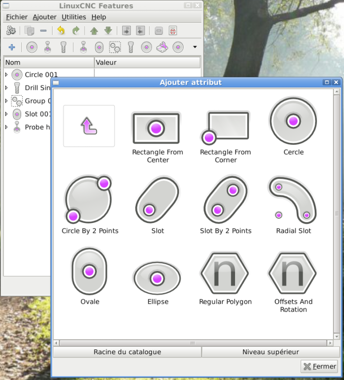
About 'cutting-params and diameter', look at my screenshot showing all kind of lines, the top one. Far right is a rectangle where I set tool diameter compensation. The outside line are what the final cut will leave and the inner lines are the tool path. Same for the circle (far left) which is based on helix. So when I want a rectangle 10X20, this is the size I set, I do not have to calculate tool diameter. I agree that code is written once but what is interesting with tool compensation is that it will follow any line correctly. You have to do the tool change first.
I do not have a tool changer and am writing code for using my probe to reset Z position like in those videos
and my probe is this one
www.micro-machine-shop.com/3D_digitizing.htm
110 USD from
wildhorse-innovations.com/index.php?_a=viewProd&productId=80
I will look to modify the code to use same "menu.xml" for menu or icon view interface
Regards
Fern
Please Log in or Create an account to join the conversation.
- FernV
-
- Offline
- Platinum Member
-
- Posts: 457
- Thank you received: 124
I was able to load your menu with minimal changes to it, but unable to load any ini, because I think it is because your folders structure is more complex than mine. Also, when loading the icons, it was the large image that loaded. First see what needed to be changed in the variables to set the path and what it looks like when loaded. Subfolders are possible in all path, it then depends of the ini


And writing code to change tools any number of times in a job and use the probe to compensate for length is a complete success
Regards
Fern
Please Log in or Create an account to join the conversation.
- turbospeedskater
- Offline
- New Member
-
- Posts: 16
- Thank you received: 0
sorry fo no reaction from my side...
In the moment I have to fight with another piece of software (BLDC-controller),
that must be finished on Monday.
Hopefully I have some time to go through all the posts during the weekend.
best regards,
Martin.
Please Log in or Create an account to join the conversation.
- FernV
-
- Offline
- Platinum Member
-
- Posts: 457
- Thank you received: 124
It is possible to use larger icons in the menu like this
OR
combine menu AND iconview like this
It is just a matter of selecting True or False in features.py
What do you think ?
Best regards
Fern
Please Log in or Create an account to join the conversation.