NativeCAM is Features renamed
- kramdradoow
- Offline
- New Member
-

Less
More
- Posts: 17
- Thank you received: 1
10 Oct 2016 18:00 - 10 Oct 2016 18:19 #81519
by kramdradoow
Replied by kramdradoow on topic NativeCAM is Features renamed
Fern, Great work.
First some background. I am running 2.7.7 from a fresh install from a live dvd and have accepted/incorporated all of the system identified updates. I ran sudo python setup.py c to undo previous version. I deleted my previous "hacked" subdirectory structure and installed the new version from clone instead of zip file. I ran sudo python setup.py and successfully launched lcnc with NativeCAM embedded. I am running AXIS.
Some observations similar to Floris video.
When I first attempted to load a file from the examples subdir, I saw the tool paths fine but no outline of the workpiece. I also tried to create a new project with a new workpiece. No luck there.
Then I found if I added a tool BEFORE I added the workpiece I could successfully add the workpiece and modify values. So I was able to add the workpiece, tool and some basic geometry but only if I loaded them in the order described above. However, I still had no workpiece visible on the AXIS toolpath screen. After watching Floris video I selected the "toggle skip line" icon and magic happened. I now can see the outline of the workpiece.
Once I established this very first project and saved as default template I no longer have to think about this. (But I wonder if I have to follow that order if I choose a new project without having defined a default template.)
For new folks trying NativeCAM, maybe my observations will help others out. I also don't know if this is your intended process because I ran gmocapy sim and did not see that if mattered what order I created workpiece/tool in nor did I need to select any "skip line". icon. Indeed, I don't even know if there is one on gmocapy.
Keep up the good work. I anxiously await your lathe updates. I run a mill and a lathe using axis cnc and can't wait for lathe. Plasma... no need for me yet.
Mark
I just verified that without a default template saved, I cannot create a workpiece until after I create a toolchange. Hope observations helps.
Last edit: 10 Oct 2016 18:19 by kramdradoow. Reason: updated comments
The following user(s) said Thank You: FernV
Please Log in or Create an account to join the conversation.
- newbynobi
-
- Offline
- Platinum Member
-

Less
More
- Posts: 1931
- Thank you received: 394
10 Oct 2016 19:40 #81525
by newbynobi
Replied by newbynobi on topic NativeCAM is Features renamed
Hallo Fern,
I just tried NativCAM on a real machine with very strange behavior!
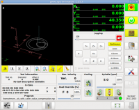
I tried to machine the part from the previous screen shot.
My 4.2 mm drill has a tool length offset of -6.25 mm. I touched off with tool 1 (tool length offset = 0), than I loaded tool T7 M6 G43 with offset -6,25 and started the code (just drilling), the tool begins drilling about the tool compensation over the workpiece and thats why it would not go through the workpiece.
Very strange, as If i unload the tool with T0 M6 G49 before starting the code, it is fine.
Next, after finishing the part, I just mounted a new part of material and pressed start again, but then your code moved the zero point of the part! The code finished with the tool in position X90 Y0 and after the restart the position X90 was X0! Also the tool compensation made strong behaviors.
So I added as last code T0 M6 G49 G0 X0 Y0 and could make my three parts.
Have you ever noticed that? I made a new clone on my productive machine, running fresh master with rip-environment (I need my baby gmoccapy 2.1.5 for testing on that machine).
I followed the instructions of readme.dev. (By the way you missed to mention, that you need to copy the ui file to the config dir)
If you need more details, I will be pleased to help, as I will go on using NativeCAM.
Norbert
I just tried NativCAM on a real machine with very strange behavior!
I tried to machine the part from the previous screen shot.
My 4.2 mm drill has a tool length offset of -6.25 mm. I touched off with tool 1 (tool length offset = 0), than I loaded tool T7 M6 G43 with offset -6,25 and started the code (just drilling), the tool begins drilling about the tool compensation over the workpiece and thats why it would not go through the workpiece.
Very strange, as If i unload the tool with T0 M6 G49 before starting the code, it is fine.
Next, after finishing the part, I just mounted a new part of material and pressed start again, but then your code moved the zero point of the part! The code finished with the tool in position X90 Y0 and after the restart the position X90 was X0! Also the tool compensation made strong behaviors.
So I added as last code T0 M6 G49 G0 X0 Y0 and could make my three parts.
Have you ever noticed that? I made a new clone on my productive machine, running fresh master with rip-environment (I need my baby gmoccapy 2.1.5 for testing on that machine).
I followed the instructions of readme.dev. (By the way you missed to mention, that you need to copy the ui file to the config dir)
If you need more details, I will be pleased to help, as I will go on using NativeCAM.
Norbert
The following user(s) said Thank You: FernV
Please Log in or Create an account to join the conversation.
- eFalegname
-

- Offline
- Elite Member
-

Less
More
- Posts: 252
- Thank you received: 30
10 Oct 2016 19:53 #81526
by eFalegname
Replied by eFalegname on topic NativeCAM is Features renamed
Fern, I think that to understand better the workflow it would be nice to rearrange the icons, for example, the first icon would allow to create the workpiece, then the second comments, the third writing some gcode lines (parameters, preamble), the next the tool change, the other the creation of geometry and groups and so on in a simple way to illustrate the workflow in NativeCAM.
Floris
Floris
Please Log in or Create an account to join the conversation.
- FernV
-
 Topic Author
- Offline
- Platinum Member
-
Less
More
- Posts: 457
- Thank you received: 124
10 Oct 2016 20:51 #81527
by FernV
if you want to load it and see how little has been done the command from the ncam directory is :
linuxcnc configs/sim/axis/ncam_demo/lathe.ini
I do not want to support it for now because it has a lower priority and I guess you know more about using a lathe than I
Regards
Fern
Replied by FernV on topic NativeCAM is Features renamed
I may regret it but I uploaded files and a new ini for axis lathe only and inchI've checked out a commit of nick before you started the work, and it does have all these lathe features but, it opens, I can enter values for stuff but I can't import the code into emc2.7.7
If you have any advices on that I would be grateful!
")
if you want to load it and see how little has been done the command from the ncam directory is :
linuxcnc configs/sim/axis/ncam_demo/lathe.ini
I do not want to support it for now because it has a lower priority and I guess you know more about using a lathe than I
Regards
Fern
Please Log in or Create an account to join the conversation.
- FernV
-
Topic Author
- Offline
- Platinum Member
-
Less
More
- Posts: 457
- Thank you received: 124
10 Oct 2016 20:54 #81528
by FernV
Fern
Replied by FernV on topic NativeCAM is Features renamed
The reason why I did not give more info on how to do it is because it saves some values twice and I did not have a chance to verify if it affects the setting you would have to do, which I promise you will find very simpleFern, I think that to understand better the workflow it would be nice to rearrange the icons, for example, the first icon would allow to create the workpiece, then the second comments, the third writing some gcode lines (parameters, preamble), the next the tool change, the other the creation of geometry and groups and so on in a simple way to illustrate the workflow in NativeCAM.
Floris
Fern
Please Log in or Create an account to join the conversation.
- absolut15
- Offline
- Junior Member
-

Less
More
- Posts: 28
- Thank you received: 2
10 Oct 2016 21:09 - 10 Oct 2016 21:14 #81529
by absolut15
Replied by absolut15 on topic NativeCAM is Features renamed
Hi fernando.
I only say thank you and wish your and your familie all the best.
After i get nativecam working today , i am sure lcnc gets a lot more atractive because of you and your work.
Have a nice time and greedings from austria.
Florian
I only say thank you and wish your and your familie all the best.
After i get nativecam working today , i am sure lcnc gets a lot more atractive because of you and your work.
Have a nice time and greedings from austria.
Florian
Last edit: 10 Oct 2016 21:14 by absolut15.
The following user(s) said Thank You: FernV
Please Log in or Create an account to join the conversation.
- FernV
-
Topic Author
- Offline
- Platinum Member
-
Less
More
- Posts: 457
- Thank you received: 124
10 Oct 2016 21:39 #81530
by FernV
THIS HAS TO BE DONE WHEN LINUXCNC IS CLOSED OR THE FILE WILL BE OVERWRITTEN
NOTE THAT THE TOOLBAR WILL BE MOST USEFULL WHEN WE HAVE THE RIGHT ICON ON IT. MANY ARE NEEDED AND I AM NOT GIFTED AT DRAWING. YOU CAN IDENTIFY EASILY WHICH ONE I ADDED
From ncam_demo/ncam/catalogs/mill/ open quick_access.lst
(if the file does not exist, it will be created the first time you select a subroutine, open linuxcnc with the ini you want and simply select an item then exit)
The INFO section says it all :
"columns are : source, total usage, last time used and order of preference
Delete this file to reset or edit rank in descending order"
You should recognize by the files name what you want : circle.cfg, end-mill-change.cfg, etc...
Find the line of the one you want leftmost like end-mill-change.cfg (IMHO it should be the one). The last number of the line is the order. Set the highest number for it like 10000. Find the second you want and assign the second order like 9000 and so on.
Save the file and start lcnc. The order should be what you set and will not change on anything you set the order
Fern
Replied by FernV on topic NativeCAM is Features renamed
I checked and I found that the data in double is only in my Dropbox directory. My office PC is Win10 and I often develop/debug the ncam.py on that platform and since it does not recognize linux path very well, it saves the path to cfg files in the way it interprets it and when working with the same ini file from my mill pc (linux of course) it saves the path from it's point of view. The result is 2 references for one file. On my home PC it is not the case and paths are saved only once, so I do not have anything to change and I will explain how to order the quick access tool bar.The reason why I did not give more info on how to do it is because it saves some values twice and I did not have a chance to verify if it affects the setting you would have to do, which I promise you will find very simple
THIS HAS TO BE DONE WHEN LINUXCNC IS CLOSED OR THE FILE WILL BE OVERWRITTEN
NOTE THAT THE TOOLBAR WILL BE MOST USEFULL WHEN WE HAVE THE RIGHT ICON ON IT. MANY ARE NEEDED AND I AM NOT GIFTED AT DRAWING. YOU CAN IDENTIFY EASILY WHICH ONE I ADDED
From ncam_demo/ncam/catalogs/mill/ open quick_access.lst
(if the file does not exist, it will be created the first time you select a subroutine, open linuxcnc with the ini you want and simply select an item then exit)
The INFO section says it all :
"columns are : source, total usage, last time used and order of preference
Delete this file to reset or edit rank in descending order"
You should recognize by the files name what you want : circle.cfg, end-mill-change.cfg, etc...
Find the line of the one you want leftmost like end-mill-change.cfg (IMHO it should be the one). The last number of the line is the order. Set the highest number for it like 10000. Find the second you want and assign the second order like 9000 and so on.
Save the file and start lcnc. The order should be what you set and will not change on anything you set the order
Fern
The following user(s) said Thank You: eFalegname
Please Log in or Create an account to join the conversation.
- FernV
-
Topic Author
- Offline
- Platinum Member
-
Less
More
- Posts: 457
- Thank you received: 124
10 Oct 2016 22:12 #81531
by FernV
Fern
Replied by FernV on topic NativeCAM is Features renamed
This should not be, Be assured that I read/listen to all feedback and will correct asap.When I first attempted to load a file from the examples subdir, I saw the tool paths fine but no outline of the workpiece. I also tried to create a new project with a new workpiece. No luck there.
Then I found if I added a tool BEFORE I added the workpiece I could successfully add the workpiece and modify values.
This is the behavior we wantSo I was able to add the workpiece, tool and some basic geometry but only if I loaded them in the order described above. However, I still had no workpiece visible on the AXIS toolpath screen. After watching Floris video I selected the "toggle skip line" icon and magic happened. I now can see the outline of the workpiece.
Your default template will load everytime you click "New Project"Once I established this very first project and saved as default template I no longer have to think about this. (But I wonder if I have to follow that order if I choose a new project without having defined a default template.)
The button is visible only when you are in auto mode not mdi. It is on the lower bar at about 1/3 from the rightFor new folks trying NativeCAM, maybe my observations will help others out. I also don't know if this is your intended process because I ran gmocapy sim and did not see that if mattered what order I created workpiece/tool in nor did I need to select any "skip line". icon. Indeed, I don't even know if there is one on gmocapy.
Fern
Please Log in or Create an account to join the conversation.
- kramdradoow
- Offline
- New Member
-
Less
More
- Posts: 17
- Thank you received: 1
10 Oct 2016 22:19 #81532
by kramdradoow
Replied by kramdradoow on topic NativeCAM is Features renamed
Thanks Fern. I successfully loaded up axis sim with embedded lathe. I have had no time to examine it but am grateful that you shared this. I'm no programmer so I can be of no help except to try your programs out. I do recognize you will not be supporting lathe yet so I won't bother you with requests and questions.
Mark
Mark
Please Log in or Create an account to join the conversation.
- FernV
-
Topic Author
- Offline
- Platinum Member
-
Less
More
- Posts: 457
- Thank you received: 124
10 Oct 2016 22:27 #81533
by FernV
Please continue giving me feedback
Best regards
Fern
Replied by FernV on topic NativeCAM is Features renamed
I never worked with tool length compensation yet, be carefull and keep me inform of your observationsI just tried NativCAM on a real machine with very strange behavior!
I tried to machine the part from the previous screen shot.
My 4.2 mm drill has a tool length offset of -6.25 mm. I touched off with tool 1 (tool length offset = 0), than I loaded tool T7 M6 G43 with offset -6,25 and started the code (just drilling), the tool begins drilling about the tool compensation over the workpiece and thats why it would not go through the workpiece.
If you cancelled the job, it is possible that it stayed in G57 instead of restoring G54 coords offsets. Refreshing the file corrects that.Very strange, as If i unload the tool with T0 M6 G49 before starting the code, it is fine.
Next, after finishing the part, I just mounted a new part of material and pressed start again, but then your code moved the zero point of the part! The code finished with the tool in position X90 Y0 and after the restart the position X90 was X0! Also the tool compensation made strong behaviors.
So I added as last code T0 M6 G49 G0 X0 Y0 and could make my three parts.
Have you ever noticed that?
Right the information is not in README-DEV but commented in the [DISPLAY] section of all ini filesI made a new clone on my productive machine, running fresh master with rip-environment (I need my baby gmoccapy 2.1.5 for testing on that machine).
I followed the instructions of readme.dev. (By the way you missed to mention, that you need to copy the ui file to the config dir)
Please continue giving me feedback
Best regards
Fern
Please Log in or Create an account to join the conversation.
Time to create page: 0.299 seconds