Search Results (Searched for: )

  • nicklego
18 Mar 2026 17:14
Motor timing help was created by nicklego
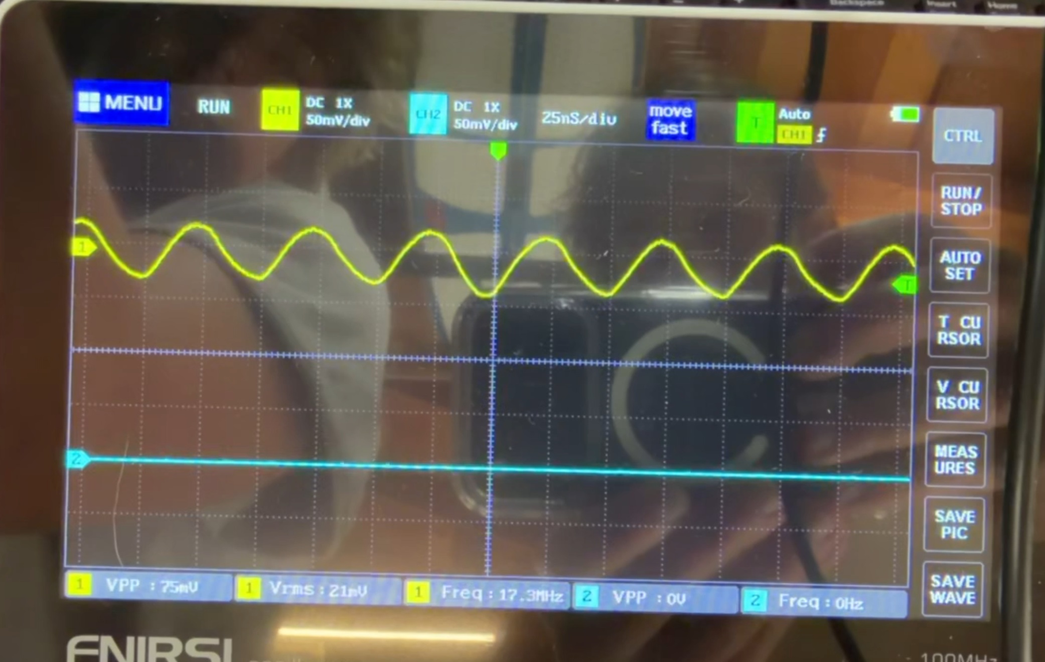
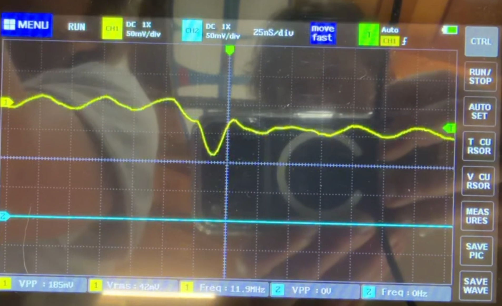
 Hi, I'm trying to get my motors running with LinuxCNC, and I have an old controller for the machine that can move the motors, but the card reader on it is broken. I have tried many times to get it working with LinuxCNC, but now I've tried to diagnose it with an oscilloscope on the old controller. For the x-axis output, the step pin outputs a constant 20MHz signal when not being told to move, but when being told to move, it outputs a 12MHz signal. Image 1 is the motor not moving (Consistent wave), and image 2 is the motor moving (weird-looking wave). I took a video of them side by side and is linked to a google drive. If anyone knows how I can replicate this signal/frequency in LinuxCNC, that would be greatly appreciated. Thanks. Link to video -->  drive.google.com/file/d/1qQ6TFAT_yjkfDdm...Lns/view?usp=sharing
Image 1 -->      Image 2 --> 
  • PCW
18 Mar 2026 17:07
Before you start LinuxCNC, does red LED CR11 (above TB4) Illuminate?
 
  • georgio
18 Mar 2026 17:01
Hi PCW,
I have attached the linuxcnc report. I put it for line 36 in hal but all of the other inputs 05-09 were the same errors. No there aren't any red led's on the board at that location with the error i get there will be one in amonst the boot up led's.
Thanks
  • PCW
18 Mar 2026 15:31
When you say you have an error,
Please please copy/paste that error
in your post.

It's nearly impossible to diagnose the issue
without accurate error reporting.

Also do you have a red LED (CR11) illuminated
above the Spindle connection (TB4) ?

 
  • miniwini
18 Mar 2026 15:27 - 18 Mar 2026 15:31
LinuxCNC 2.98 - Ethercat - ProbeBasic was created by miniwini
Hi there!

my Raspberry Pi5 died so i needed to setup thing new, but I can´t get it working anymore. It worked before... 

I have two Ethercat modules which need "speical care"
1. its the external "EP1809-0021" this is identical to the EL1809, so just replicating the last line in the el1xxx.c with the correct PID, works
2. the EL2564, this is a dedicated "driver" which is copied into the linuxcnc-ethercat/src/devices which gets compiled, works... 

LinuxCNC runs in the SIM Modes... also with ProbeBasic
EtherCat works - ethercat master and slave commands...
but LinuxCNC with ProbeBasic and Ethercat doesn´t want to start.
Code:
LinuxCNC Ethercat crashed with signal 11 -- STACK TRACE START 0    /usr/lib/linuxcnc/modules/lcec.so(+0xfcbc) [0x7f72cb8f3cbc] 1    /lib/x86_64-linux-gnu/libc.so.6(+0x3c050) [0x7f72cc759050] 2    /lib/x86_64-linux-gnu/libethercat.so.1(ecrt_slave_config_pdos+0x2f) [0x7f72cb8b652f] 3    /usr/lib/linuxcnc/modules/lcec.so(rtapi_app_main+0x40a) [0x7f72cb8f4f68] 4    /usr/bin/rtapi_app(+0xbd67) [0x558070fe7d67] 5    /usr/bin/rtapi_app(+0xc6be) [0x558070fe86be] 6    /usr/bin/rtapi_app(+0xccbc) [0x558070fe8cbc] 7    /usr/bin/rtapi_app(+0x7a04) [0x558070fe3a04] 8    /usr/bin/rtapi_app(main+0x70f) [0x558070fe348f] 9    /lib/x86_64-linux-gnu/libc.so.6(+0x2724a) [0x7f72cc74424a] 10    /lib/x86_64-linux-gnu/libc.so.6(__libc_start_main+0x85) [0x7f72cc744305] 11    /usr/bin/rtapi_app(_start+0x21) [0x558070fe38f1] -- STACK TRACE END twopass: load_the_modules cmd=<orig_loadrt lcec> waitpid failed /usr/bin/rtapi_app lcec /usr/bin/rtapi_app exited without becoming ready insmod for lcec failed, returned -1

Here you can see my terminal-log when starting LinuxCNC
 

File Attachment:

File Name: message.txt
File Size:6.45 KB

here you see my Ethercat terminal Outputs...
Code:
cnc@linuxcnc:~$ ethercat slaves  0  0:0   PREOP  +  EK1100 EtherCAT Coupler (2A E-Bus)  1  0:1   PREOP  +  EL1018 8K. Dig. Eingang 24V, 10�s  2  0:2   PREOP  +  EL1018 8K. Dig. Eingang 24V, 10�s  3  0:3   PREOP  +  EL2024 4K. Dig. Ausgang 24V, 2A  4  0:4   PREOP  +  EL2024 4Ch. Dig. Output 24V, 2A  5  0:5   PREOP  +  EL2008 8K. Dig. Ausgang 24V, 0.5A  6  0:6   PREOP  +  EL2008 8K. Dig. Ausgang 24V, 0.5A  7  0:7   PREOP  +  EL2034 4K. Dig. Ausgang 24V, 2A, Diagnose  8  0:8   PREOP  +  EL2809 16K. Dig. Ausgang 24V, 0.5A  9  0:9   PREOP  +  EL2809 16K. Dig. Ausgang 24V, 0.5A 10  0:10  PREOP  +  EL2809 16K. Dig. Ausgang 24V, 0.5A 11  0:11  PREOP  +  EL1819 16K. Dig. Eingang 24V, 10�s 12  0:12  PREOP  +  EL1819 16K. Dig. Eingang 24V, 10�s 13  0:13  PREOP  +  EL2564-0010 4 K. LED-Ausgang, 8...48 V DC, 3 A, RGBW, Common Ca 14  0:14  PREOP  +  EL3202 2K.Ana. Eingang PT100 (RTD) 15  0:15  PREOP  +  EL3014 4K. Ana. Eingang 0-20mA DIFF 16  0:16  PREOP  +  EL3052 2Ch. Ana. Input 4-20mA 17  0:17  PREOP  +  EK1122-0008 2-Port EtherCAT-Abzweig M8 18  0:18  PREOP  +  EP1018-0001 8 K. Dig. Eingang 24V, 10�s, M8 cnc@linuxcnc:~$ 

the EP1809 wasn´t connected...

so what can it be? I followed the "EtherCat installation from repositories" from Rod... i tried multiple images, 2.94~2.98 on Bookworm and Trixie... 

thank you

miniwini

  • currinh
18 Mar 2026 15:27
Replied by currinh on topic Trouble with XFCE (trixie) timed logouts
I have it running well with linuxcnc 2.9.4. Don't really want to over write that. But, I'll put a different hard drive in and load up 2.9.8 to see if this works.

I tried turning off Power Management in the settings menu which gave the original problem, auto login/logout loop. Where do you "set times to zero"? Is that in the window just below the Power Management slider/button? If via setting parameters in a config file or via terminal command where and how?

I don't see anything I recognize as power management in Rod's script.

Thank you. Hugh
  • georgio
18 Mar 2026 15:05
I just figured out what the gpio pins are and they are if iam correct the 50 pins on P1 and P2 halshow was not showig any sserial port pins. That is probably why the pin do not exist errors I was getting is from.
Just a thought
  • georgio
18 Mar 2026 14:47
Thank you for your response PCW. I have checked and there is field power of 24v across pins 1&8 it is also tranfered to the nearby power block can't remember its tb number but done as mentioned in posts and manuals.
Thanks
  • PCW
18 Mar 2026 14:37
The field I/O (TB4,5,6) is not GPIO.

If you assign TB5 or TB6 I/O pins or spindle (TB4) pins in pncconf and
you get pin not found errors, this most likely means that you do not
have field power applied (TB1 = ORANGE  connector)
  • Alfapro
18 Mar 2026 14:07
Replied by Alfapro on topic Buffered G-code streaming from Python
So it’s actually possible. For some reason I thought MDI only accepts a single command and then blocks until it’s finished.
I’m working on my bachelor’s thesis about a 6-DOF robotic manipulator, and I’m planning to implement something higher-level than G-code. I assumed I’d first have to fully translate my logic into G-code and then execute it, but now I’m thinking of handling the logic in Python and sending commands directly to LinuxCNC instead.
Thanks for the help!
  • jlfauvel
18 Mar 2026 13:55
... very technical, but thanks anyway. I willl take a serious look at your post. By the way, yesterday I managed to eliminate the "noise" from the X servo. Now I just need to adjust the movement smoothly.
  • georgio
18 Mar 2026 13:16
forgot to mention that in halshow i could not see any action on pins the only ones i could see were gpio pins and it listed 50 pins. Just for curiosity i looked at all 50 of the pins and tried activating the limit switchs and saw no change
  • georgio
18 Mar 2026 13:11
Startiing on line 34 of hal limits not existing pin does not exist. I commented out all six lines after reltating to non existing pins to get thru with no errors. I checked these pins on TB6 04-09 and they all has voltage of 24v until activated then went to aprox .4v.There may be an issue with the board.
Thanks PCW
  • hellvetica
18 Mar 2026 12:50
Replied by hellvetica on topic halui: updateStatus: status buffer is not valid
Hi thanks for the reply.
I found where it's printed but my question is what could cause the status buffer to be invalid after ~1hr of working flawlessly?
Is it possible it's some sort of hardware/memory corruption issue?
  • mm26
18 Mar 2026 12:15
I was at exactly same point yesterday.
Everything runs perfectly until i add the spindle output.
I figured out that the spindle outputs are on the second half of the board which is internally connected by sserial. As I was testing everything on my desk, I just powered the board via the 5V supply. After digging deeper into the manual, I figured out that the field power needs to be applied as well. Some more LED lighted up, board was working :)

hope this helps
Displaying 5761 - 5775 out of 11814 results.
Time to create page: 0.262 seconds
Powered by Kunena Forum