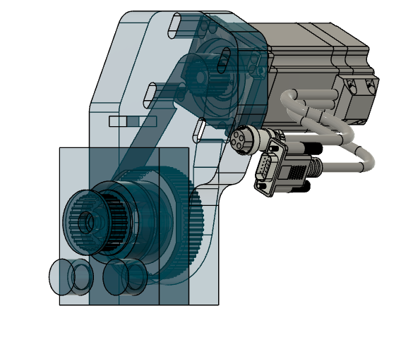
Y-axis:
3:1 reduction is fairly easy to do. Motors can be flipped around so the output shaft points outboard, with the motor housing inboard using an off-set bracket that puts the motor behind the gantry. Add a larger pulley to the drive pinion and you'll have an intermediate belt between the motor and the drive system.
X-axis:
Not so easy as you don't have room on the gantry to 'flip' the motor around like on the Y above. I'd suggest changing to a ballscrew for the X-axis for a couple reasons:
- Stiffer than a belt
- Even with a no-backlash belt system, there is still compliance in the belt as the teeth flex. Belts work rather well for plasma's and lasers, but the cutting forces on a router/mill will expose the problems with belt tooth compliance. You can't eliminate this, just minimize it with larger belt profiles, wider belts, and more teeth engaged with the various pulleys.
- Doesn't distort the gantry
- Tensioning the X-belt will/does bend the gantry and perhaps contributes to linear guide friction inconsistencies.
- A ballscrew won't distort the gantry
- Easy to achieve the mechanical reduction. A 16mm dia, 10mm pitch ballscrew is fairly inexpensive. Probably less than (or close to) the cost of additional pulleys and belts, and the 10mm pitch means your motors won't be at some screaming RPM as with a 5mm pitch.
Or... just put ballscrews on all three joints. No gearboxes needed, no pulleys, vastly improved stiffness, backlash easily managed.
And yes, you'll probably run in to the PS voltage ceiling one you get some mechanical advantage and need more RPM.