Thank you for looking at the design. Always good with new insights.
I can go with another resistor for added safety. Looked around a bit, and that will require a bit deeper study it look like. Not so easy to find in the sources I use. The most professional source I use is tme.eu. The only wire wound resistors at 100 kOhm they had would just fit in my hand.
Today, the resistor is chosen to operate with 500V, and 100kOhm is chosen for the heat output it generates.
I was thinking about the high voltage aspect when designing the board.
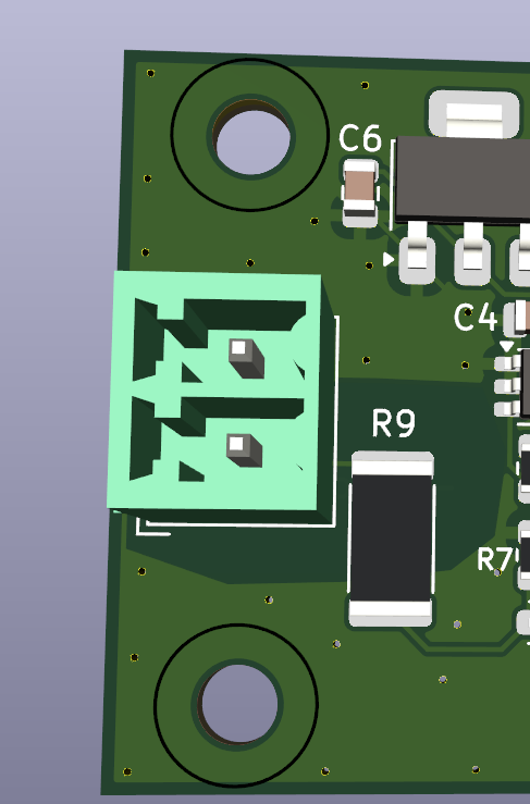
In this view you can see the short wire between the connector and the resistor. As I see it this will act as a fuse and blow out at high currents entering the board. Isolated area around the voltage parts. Hopefully any damage and malfunction will stay on the left side of the isolation barrier.
That's also why I am redesigning it.The intention was to have the ground planes electrically connected to the work piece. As it is now the ground planes are connected to the electrode. That small image is from the new design, also the high voltage part of the resistor tucked away behind the connector so shouldn't be very easy to reach with fingers.
The parts cost of one mini-board is around 10 USD/EUR so replaceable. I don't want a failure on the mini-board to break the EtherCAT board though, that's a bigger deal if that happens.
Thanks again for giving my brain some exercise.
So a new design has been made - thanks to an electronics engineer who helped - with reversed polarity for the torch voltage, well, everything is internal to the board. Should be safer, better. Just ordered new circuit boards. Somewhere after March 10th they might show up.