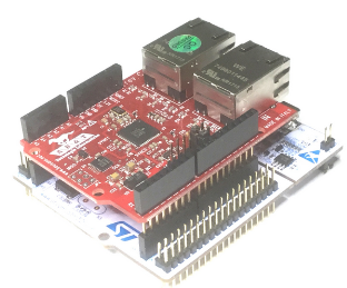
EtherCAT plasma torch voltage reader

More
1 year 8 months ago #322254 by Hakan
I see, a bit like EasyCAT kind but for the voltage reader.
 

I am more into putting the torch voltage reader components onto the EaserCAT board.
Now when I have looked at it I am not so worried about the voltage levels and that.
One just need to take some precautions.
And if I understand right, most new plasma cutters gives out scaled down voltage
so it is more to handle the floating voltage, and this circuitry does that.
The following user(s) said Thank You: rodw

Please Log in or Create an account to join the conversation.

More
1 year 8 months ago #322265 by RDA
Looks good. I dont think you have issues with the voltage levels. In another thread I said I would scope out the work to electrode voltage to show what those voltages are, but unfortunately I have not had the chance, maybe next week.
When you use the divided arc voltage, you could put this design in to your easercat pcb, as in you dont need it to be separate.
If you find a decent 16-bit one example ADS1114IDGST then it might be worth the money. The 16-bit one gives you more opportunities if you want to make some additional features in the future, its quite a bit more expensive I know.
For the OP-amp if you find something with more tolerance in the input, that would make it safer but may not be worth it.

If you can give me an email address where you can be reached, I can share you an ohmic sensing schematic if you want to try it out and then share to the community.

Please Log in or Create an account to join the conversation.

More
1 year 8 months ago - 1 year 8 months ago #322269 by Hakan
From what I have seen during the tests the torch voltage is below 200V. During start and piercing it easily goes up to 180V but not above that.
It cuts around 100V. Thin material in the 80s-90s, thick in the 110s.
The arc is also DCEN, DC electrode negative, I have been told. The work piece ground is not connected to mains ground.

200V isn't uncommon to have on a PCB, mains 230V AC is common here. My understanding is that with enough isolation distance it is fine. And the whole ADC side is isolated.

I think an ADS1115 can be used just as well, ebay aliX amazon are full of them at super low cost. To go with the 11-bit version meant that I get 3.3 kHz sample time. The ADS1115 is only 860 Hz max. That was the main factor. For the ADS1xxx ADCs one need to put them in continuous conversion  mode or the time to get a value is terrible, several milliseconds. In continuous mode its 150 microseconds. I know now how to read the ADS1014 which is actually two channels A0 A1, and I think it would be possible to use the ADS1115 with 15-bit resolution in continuous mode reading one differential channel (between A0 and A1). How important is updating exactly every 1 ms with a new value? It can't be that important, there is a bit of noise in the voltage and to read the same value every 7th time can't be that bad, can it? Anyway, that was the decision point and I choose 11-bit resolution, one differential channel and 3.3 kHz updating rate. The footprint is the same for those ADS1xxx so one can easily solder in another one, and reprogram. It is actually only something like 10 lines of code for the ADC.

The BAT54S is there to protect the input of the op-amp. Don't know much about that, it is something I found. The lmv321 was also not actively chosen but was known to work. I do see non-linearity at the very bottom of the range, so it isn't fully rail-to-rail. They aren't as I understood it, and it isn't important, it isn't working close to the rail voltages. But it means the display says 2V when it is 0V, but it should be linear above say 5V (in the 0-200V range).

Do you have an ohmic sensing solution when the plasma nozzle is the same polarity as the work piece?
I can see no change in voltage when the torch touches the work piece. I was hoping for that, but no.
I am very interested to include that.
Last edit: 1 year 8 months ago by Hakan.

Please Log in or Create an account to join the conversation.

More
1 year 8 months ago #322294 by rodw
Best practice per the Hypertherm docs is to have a star ground point on your machine.
www.hypertherm.com/Download?fileId=HYP103900&zip=False
Most plasma machines have a grounding point. It and the work lead should be connected to this star ground.
Also there shouldd be a seperate groound wire for every motor that leads back to the star ground. The purpose of this is to provide a path for EMI that is not going through all of your linear carriage bearings which adds to noise and damage.

Finally, ohmic sensing will only work  if the torch tip is shielded. You can't do it if the tip is exposed. This is because the electrode is shorted in the torch internally to the work piece until the arc is initiated at which time it blows back by air to  clear the short.

Who said plasma was easy?

Please Log in or Create an account to join the conversation.

More
1 year 8 months ago #322296 by rodw
EDIT: with modern plasma machines without HF start, its not necessary for a seperate grounding stake

Please Log in or Create an account to join the conversation.

More
1 year 8 months ago #322300 by Hakan
It makes sense to have it that way. However, in my Herocut 55i plasma cutter, the work lead or ground clamp is not automatically connected to mains ground.
And that also means that the plasma electrode is at -100 Volts or so. So when connecting it you have to be a little careful and not just assume that the electrode is the positive one because it is not. In this case. My machine has the polarity of the pins in the torch voltage connector well documented and is just a matter of following.
About ohmic sensing, that was my assumption too. A glimmer of hope was born when RDA mentioned it though.

Please Log in or Create an account to join the conversation.

Time to create page: 0.416 seconds
Powered by Kunena Forum