Puma 560 simulation using pumakins
- andypugh
-

- Offline
- Moderator
-

Less
More
- Posts: 19875
- Thank you received: 4642
27 Oct 2015 00:33 #64316
by andypugh
Don't worry, we are on it:
thread.gmane.org/gmane.linux.distributions.emc.devel/15358
Replied by andypugh on topic Puma 560 simulation using pumakins
Ok Andy... you are well over my head at this point.
Don't worry, we are on it:
thread.gmane.org/gmane.linux.distributions.emc.devel/15358
Please Log in or Create an account to join the conversation.
- robottom
- Offline
- Senior Member
-

Less
More
- Posts: 53
- Thank you received: 4
30 Oct 2015 22:05 #64524
by robottom
Replied by robottom on topic Puma 560 simulation using pumakins
Hi Andy and Jerry,
a lot of usful thoughts on how to home the Puma. In parallel I'm investigating if I can use a Arduino Nano to do parts of the homing procedure. I have only one parport on my LinuxCNC laptop and not enough pins for all the needed lines. In addition my cable from the controller to the Puma arm also would need a lot of additional wires (at least 6 analog lines for the potis and 6 for the index signals). So I thought to put a Arduino in the arm to connect to the potis to the analog input and the index to digital inputs of the Nano board and need the USB connection to my laptop and only one (or a few) inputs to the parport (for the real time signals of a common index).
My idea is to home each axis after another with potis + index signal to prevent the arm to do big moves during homing. Via USB I would transfer all the poti values and which index signal was fired. One input line on the parport would be required to signal in real time that there is an index reached to stop immediately the homing move and go e.g. from CW to CCW for a very slow precision move to hit the index again. The USB signals non-real-time would be sufficient to calculate from the poti signal and the index for a certain joint the exact position.
My question to you is: As far as I understood I can implement my own homing procedure (e.g. read to from USB, initiate the moves and calculate the positions). Is this correct or not possible to implement his own homing?
Many thanks, Thomas
Please Log in or Create an account to join the conversation.
- Askjerry
-

- Offline
- Elite Member
-

Less
More
- Posts: 239
- Thank you received: 31
31 Oct 2015 09:59 #64538
by Askjerry
Replied by Askjerry on topic Puma 560 simulation using pumakins
My take on this is that AXIS can be configured to allow it to run G-Code without being homed.
[TRAJ]
NO_FORCE_HOMING = 1
This means that (in theory) the same pins that are used as HOME switches could be read as an input... and that G-Code could interact with them. This G-Code could do some pre-work to get the system near the home points ready for actual homing... then terminate.
The user would then click the "HOME ALL" button in AXIS which would run each joint to the nearest position where the INDEX is read as HOME.
I have somewhat of an idea how to accomplish this... but frankly to pull it all off is still above my level of expertise.
HOME INFO: linuxcnc.org/docs/html/config/ini_homing.html#_home
Please Log in or Create an account to join the conversation.
- Askjerry
-
- Offline
- Elite Member
-
Less
More
- Posts: 239
- Thank you received: 31
10 Nov 2015 22:45 #65091
by Askjerry
Replied by Askjerry on topic PUMA 560 WIRE LISTS
For anyone else interested in getting a PUMA back online... I scanned the wire lists from my PUMA manual into a PDF.
Here is a link to the file: PUMA MOTOR WIRE LIST
Hopefully someone will find it useful.
Jerry
Here is a link to the file: PUMA MOTOR WIRE LIST
Hopefully someone will find it useful.
Jerry
Please Log in or Create an account to join the conversation.
- Askjerry
-
- Offline
- Elite Member
-
Less
More
- Posts: 239
- Thank you received: 31
24 Dec 2015 04:06 - 24 Dec 2015 04:47 #67280
by Askjerry
Replied by Askjerry on topic Puma 560 simulation using pumakins
I was thinking about the homing on the PUMA... today it dawned on me that there is a variable resistor (potentiometer) attached to each motor. If this resistor was given a reference voltage and ground... the output would vary from the reference (VCC) to 0 (GND). The trick is to detect only a single point.
Using a 741 OP AMP IC, you can accomplish this fairly quickly.
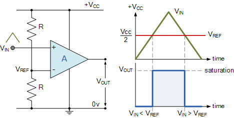
So if you use this circuit... then attach the output to an OPTO-ISOLATOR with the appropriate resistor... for example a 4N35 IC... then you get a HIGH for anything above the set point, and a LOW for anything below that point... just like you would get from a HOME switch.
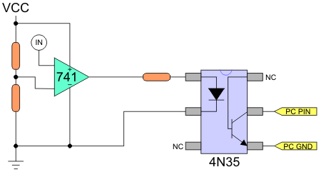
You then could replace one of the fixed resistors in the voltage divider with a 10-turn potentiometer... and really fine-tune the HOME position. Or... you could see where it stops... and just set the offset in the INI file.
In any event... it should work very well.
Thoughts?
Jerry
Using a 741 OP AMP IC, you can accomplish this fairly quickly.
So if you use this circuit... then attach the output to an OPTO-ISOLATOR with the appropriate resistor... for example a 4N35 IC... then you get a HIGH for anything above the set point, and a LOW for anything below that point... just like you would get from a HOME switch.
You then could replace one of the fixed resistors in the voltage divider with a 10-turn potentiometer... and really fine-tune the HOME position. Or... you could see where it stops... and just set the offset in the INI file.
In any event... it should work very well.
Thoughts?
Jerry
Last edit: 24 Dec 2015 04:47 by Askjerry.
Please Log in or Create an account to join the conversation.
- andypugh
-
- Offline
- Moderator
-
Less
More
- Posts: 19875
- Thank you received: 4642
24 Dec 2015 10:42 #67286
by andypugh
If you derived the V-ref from a PWM signal then you can measure the actual position, possibly to within one encoder revolution.
(This is just a roundabout way to do analogue input with a digital output)
You would only need one V-ref and a comparator for each joint.
Replied by andypugh on topic Puma 560 simulation using pumakins
Thoughts?
If you derived the V-ref from a PWM signal then you can measure the actual position, possibly to within one encoder revolution.
(This is just a roundabout way to do analogue input with a digital output)
You would only need one V-ref and a comparator for each joint.
Please Log in or Create an account to join the conversation.
- Askjerry
-
- Offline
- Elite Member
-
Less
More
- Posts: 239
- Thank you received: 31
24 Dec 2015 14:39 #67288
by Askjerry
Replied by Askjerry on topic Puma 560 simulation using pumakins
The motors have a quadrature encoder which is very accurate. You only need to find a home reference for LinuxCNC to be able to use it's homing routines. Unlike a typical milling machine which has limit switches or a home switch, the PUMA does not have that feature.
In the original controller, it had an analog to digital card that read the position, calibrated it, and moved to home... then it used the quadrature encoders. The issue wasn't getting accurate positioning data... it was finding that one location for home... without needing to modify the PUMA.
I think this would accomplish that goal... the machine would move to that location and LinuxCNC would see it as a switch tripping... which would allow normal homing activity.
Please Log in or Create an account to join the conversation.
- cncbasher
- Offline
- Moderator
-
Less
More
- Posts: 1021
- Thank you received: 202
24 Dec 2015 16:50 #67290
by cncbasher
Replied by cncbasher on topic Puma 560 simulation using pumakins
if the motors have quadrature , then does it have index also ? or only a,b
then use index for homing , ( sometimes it may mean rotating the body of the encoder to match the home position )
then count the index rotation
then use index for homing , ( sometimes it may mean rotating the body of the encoder to match the home position )
then count the index rotation
Please Log in or Create an account to join the conversation.
- Askjerry
-
- Offline
- Elite Member
-
Less
More
- Posts: 239
- Thank you received: 31
24 Dec 2015 18:03 #67293
by Askjerry
Replied by Askjerry on topic Puma 560 simulation using pumakins
I don't think there is an index... and if there were... it would pulse once per revolution. The trick is getting one, and only one logic state change across the entire range of travel. If it had an index... then the output from the circuit above and the index pulse could be routed through an AND gate... the unit would detect a high at any point where the index pule AND the circuit pulse were both high. This would occur at specific intervals all across the upper band. You would need to drive the PUMA to a point where the first signal was NOT high, then start moving forward until both outputs went high the first time.
Getting LinuxCNC set up to do that would be problematic... at least I think so. An alternative would be to set the circuit level at the very high end... near the end of travel. It would detect the AND signal... then the INI file would direct it to back off by a specified amount.
Not sure if that level of complexity would be required... although now I may have to find out. The folks who have been using my PUMA the last 6 months are returning it today... apparently the controller has now failed. If so... the cost to get it repaired would be several times the cost of building a new controller. Part of me is looking forward to that challenge... part of me wishes that the original controller and the VAL command structure were still intact. On the bright side... I may be able to replace a 70 pound noisy controller with a 15 pound quiet one. (When I can afford the 6 drivers to do so.)
Please Log in or Create an account to join the conversation.
- robottom
- Offline
- Senior Member
-
Less
More
- Posts: 53
- Thank you received: 4
24 Dec 2015 20:57 #67300
by robottom
Replied by robottom on topic Puma 560 simulation using pumakins
Hi Jerry and Andy,
very good thoughts about the homing.
First, yes the encoders do have index signals.
Best would be to do the homing similar to the original controller combining the potentiometers with the index signals at each join.
The advantage is that it can home with a very small travel at any position. But this could get a bit tricky. Most probably I have to add some coding / modification to the Linuxcnc because it would be a non-standard homing procedure. This is still an option because in the meanwhile I have set up my development envirnoment and could modify the standard code.
Maybe I will start with a standard homing using a similar schema you line out above and then later switch to a more advanced without the need to do a longer distance travel to the home position. You know these travel can often cause collisions in the working space of a 6 axis machine.
Concerning the hardware I'm currently in favor of using an Arduino instead of a discrete comparator / OP Amp with a 10 turn precision poti and and AND gate.
An Arduino Nano is much cheaper (>3 EUR) and much easier to use. It comes with >6 A/D input (for the poti signal) and >6 digital inputs for the index signal. I can easily program the arduino at any position so it creates an output for the parport to simulate a home switch.
The original Puma controller works with a translation table that assigns to various joint positions an index position and a poti value so it can home at each index signal. This is generated during the potcal procedure. I could do the same and store it into the Arduino if I implement the final solution. The arduino could transfer the joint position to the linuxcnc. But this would require more input wires than I do not have with the current 6 axis setup at one parport. Most probably I would use the Arduino USB connection to transfer the position.
For now I could start with the easy solution having a fixed home position what I can easily change in the arduino software.
Please Log in or Create an account to join the conversation.
Time to create page: 0.182 seconds