Puma 560 simulation using pumakins
- Askjerry
-

- Offline
- Elite Member
-

Less
More
- Posts: 239
- Thank you received: 31
24 Dec 2015 23:06 - 24 Dec 2015 23:08 #67305
by Askjerry
Replied by Askjerry on topic Puma 560 simulation using pumakins
Now you are onto something... but you are making it much more difficult than needed... you don't need to modify the LinuxCNC routines or anything like that... for some reason, I didn't even think about an external microprocessor... ugg.
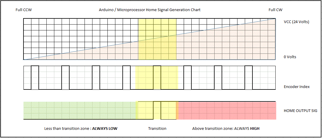
What you want to do is set the Arduino up as a "switch server"... have it look at the A/D position and the Index Signal. It will then evaluate the pulses and the A/D, and only send out a logic LOW when the correct conditions are met.
In normal LinuxCNC homing, if it gets a LOW, it considers that the limit/home switch is tripped and moves in one direction initially... if on the other hand the signal is HIGH... it moves in the opposite direction until the signal goes low... then begins the sequence of backing off, etc.
So the Arduino looks at the AD signal and if above a certain set point, sends a HIGH constantly, if below a certain set point, it sends a LOW continuously. Within a very specific range, it will toggle between the high and low ONLY when the INDEX is also present. This way, LinuxCNC will ONLY see the toggle point at a very limited point on the travel. An Arduino (or other micro) can do this across 6 axis several hundred times per second... so there would be no issue with the LinuxCNC reading the "home switch" output from the Arduino. At other times (normal use) this signal is simply ignored... the Arduino would continue to do what it does... but no action would be taken by the PC.
Upon a HOME command, LinuxCNC would evaluate the current state and act accordingly. And... as a bonus... you can programmatically set the exact trip points to fine-tune the home position to within any single INDEX point desired.
Last edit: 24 Dec 2015 23:08 by Askjerry.
The following user(s) said Thank You: robottom
Please Log in or Create an account to join the conversation.
- robottom
- Offline
- Senior Member
-

Less
More
- Posts: 53
- Thank you received: 4
25 Dec 2015 13:07 #67315
by robottom
Replied by robottom on topic Puma 560 simulation using pumakins
Hi Jerry,
thanks for detailing this out.
The complication with the code modification in LinuxCNC would only be needed in case I want to have it similar to the original controller that can home at any position of the arm with only a very little travel and not going a full travel to a single home position.
The way you describe it is the "easy" way with a single home position per joint (only disadvantage is a possible collison in the work space).
But as said I will start with the easy way first that do not require a code modification and can work with the standard home procedure.
One thing I'm not 100% clear about is the limited number of feedback lines I have with one parport. Since I'm using a 6 axis control 12 wires/lines are already in use. There are only a few ones left (max. 5) for feedback to LinuxCNC. I need to think about how I can use them efficiently for homing 6 axis.
Thomas
Please Log in or Create an account to join the conversation.
- Askjerry
-
- Offline
- Elite Member
-
Less
More
- Posts: 239
- Thank you received: 31
25 Dec 2015 14:45 - 25 Dec 2015 14:49 #67316
by Askjerry
Replied by Askjerry on topic Timing Signals and Home - PUMA
I made a chart to better show the timing...
To answer your question, likely you will need to add a second parallel port to get the proper number of input ports. Or you would need to migrate to a MESA card. Adding a second printer port is really cheap... I get them here in Austin for $10 to $15 typically, PCI style... 5 minutes to install.
Suggested Pin Assignments: askjerry.info/CNC/PUMA_PARPORT_Pin_Assignments.xls
The Spreadsheet above assumes that you would use a StainSmart Breakout Board... they are very easy to implement.
Jerry
Last edit: 25 Dec 2015 14:49 by Askjerry.
Please Log in or Create an account to join the conversation.
- robottom
- Offline
- Senior Member
-
Less
More
- Posts: 53
- Thank you received: 4
26 Dec 2015 10:40 #67336
by robottom
Replied by robottom on topic Puma 560 simulation using pumakins
thanks Jerry for the timing diagram.
For me personally there is the issue that I want to use a Thinkpad with my Puma and no desktop PC. Unfortunately there is only one parport to and no easy option to extend with a second port. Portability is one of my major requirements and this is not easy to achieve with a desktop PC. Maybe I will check for a PCMCIA2Parport card.
I guess 6 feedback wires is the minimum you would need for the homing you have in mind.
Another option for me is to go to the more sophisticated homing where I use the USB port in addition. Via parport I would only transfer the realtime signal of "index is hit". Via USB I could tranfer control data (e.g. what axis is currently homed) and back the poti A/D converted signal. In this case I would store the potcal table (which poti values correspond to which approx. position and what is the corresponding index position). I would then home each axis after another with a small travel to the next index signal for this axis. Then reading out the poti digital value and translate with the potcal table to the exact position. But this is a non-standard homing procedure would require add. code.
Does anybody know where to intervene in the LinuxCNC code to get this implemented?
Not sure if this really makes much sense or if it would be easier to get a second partport card via PCMCIA running on the Thinkpad? Currently I'm not in favor of switching to a desktop because I have quite some Thinkpads and I love especially the 10year+ R50P which the 1600x1200 flexview.
Please Log in or Create an account to join the conversation.
- Askjerry
-
- Offline
- Elite Member
-
Less
More
- Posts: 239
- Thank you received: 31
26 Dec 2015 16:24 - 26 Dec 2015 16:25 #67346
by Askjerry
Replied by Askjerry on topic Puma 560 simulation using pumakins
The other option is to share the pins used for home. You just need to make sure of two thigs...
1) Make sure no joints trigger any home when starting the sequence.
2) Make sure your home offsets are such that no home signal is engaged after being homed.
Once homed, you can move the arm to a starting position and set yhe G54 coordinates to zero. No modification would be needed. You could share the last three joints... Make a pyVCP or Glade panel to verify that the shared joints are not triggered before you start. Many times people will use one HOME switch... As long as you follow the process of making sure they are clear first you should be fine
Last edit: 26 Dec 2015 16:25 by Askjerry.
The following user(s) said Thank You: robottom
Please Log in or Create an account to join the conversation.
- robottom
- Offline
- Senior Member
-
Less
More
- Posts: 53
- Thank you received: 4
27 Dec 2015 10:34 #67368
by robottom
Replied by robottom on topic Puma 560 simulation using pumakins
good idea to add a pyVCP or Glade panel to display the status of home switches (in my case the output of the Arduino). This gives me at least the hint if I can home the machine (for the last 3 joints with shared home signal). But what to do if the shared home signal is engaged. I guess I can only move the robot (arbitrary move of the last 3 joints to get it out of the home signal) when it is homed otherwise it is locked - or I'm I wrong. Since I'm not at home I can't test.
Please Log in or Create an account to join the conversation.
- Askjerry
-
- Offline
- Elite Member
-
Less
More
- Posts: 239
- Thank you received: 31
27 Dec 2015 16:05 #67375
by Askjerry
Replied by Askjerry on topic Puma 560 simulation using pumakins
Correct. You would have to select and jog the joint a bit.
Please Log in or Create an account to join the conversation.
- andypugh
-

- Offline
- Moderator
-

Less
More
- Posts: 19863
- Thank you received: 4636
30 Dec 2015 13:31 #67511
by andypugh
It is probably cheaper to buy a dedicated PC for the Puma than to add hardware to the Thinkpad.
But expecting to run a 6DOF machine from a single parallel port is rather ambitious.
You could consider the Mesa 7i90 which expands the parallel port into 72 IO bits. You can then easily attach interface cards, including A to D interfaces (handy for the potentiometers)
I do intend to add absolute homing to LinuxCNC, but I am afraid that I will not get round to it until I need it for my current project, and I am still at the stage of machining castings at the moment.
I think that whatever I come up with will be equally applicable to your robot.
Replied by andypugh on topic Puma 560 simulation using pumakins
For me personally there is the issue that I want to use a Thinkpad with my Puma and no desktop PC. .
It is probably cheaper to buy a dedicated PC for the Puma than to add hardware to the Thinkpad.
But expecting to run a 6DOF machine from a single parallel port is rather ambitious.
You could consider the Mesa 7i90 which expands the parallel port into 72 IO bits. You can then easily attach interface cards, including A to D interfaces (handy for the potentiometers)
I do intend to add absolute homing to LinuxCNC, but I am afraid that I will not get round to it until I need it for my current project, and I am still at the stage of machining castings at the moment.
I think that whatever I come up with will be equally applicable to your robot.
Please Log in or Create an account to join the conversation.
- robottom
- Offline
- Senior Member
-
Less
More
- Posts: 53
- Thank you received: 4
02 Feb 2016 20:23 #69468
by robottom
Replied by robottom on topic Puma 560 simulation using pumakins
Hi,
I just want to give you feedback on the actual project. I implemented the homing now with the arduino nano. It was a bit more complicated than orginally thought - as always reality is different from theory.
I came across the following issues I had to solve on the arduino:
1. The A/D conversion is one of the most expensive operations on the arduino and takes ~100 micro seconds. Not too much but I need to be sure that I don't miss any of the short and sharp index signals. The arduino nano comes only with 2 interupt lines. Without connecting all the input via OR to the interrupt I have to use a fast method for the A/D conversion to be on the save side. There are possibilities on the arduino to start the A/D conversion and run the code in parallel and get the A/D values when it is ready. If you want to know how take a look at the code I attached.
2. The poti signal is not very precise while the robot/poti is moving. During halt is differs just +/-1 from the 10digit conversion. But during move it differs ofter +/-5 (or even 10). The issue is that the index signals are every 9-10 values - around the same size. So there is no way around doing average calculation. The arduino code calculates the average of 10 A/D conversion omitting the largest and smallest value. This is precise enough to use the timing schema as it was lined out by Jerry.
The whole procedure works pretty well. There is one thing I could not solve/understand: When I power the arduino from the internal 5V power supply or from an external USB power supply there are sometimes problems with the arduino program. When I plug in the arduino into a laptop it works fine (indedpendent if it is another or the same laptop where I run the LinuxCNC) - very strange. I should be related to GND since the DB25 board is decoupled via opto coupler. No idea. So I plug in the USB cable when I running the homing.
I attached the code that is still in a beta version but for those who want to take a closer look it should give you an idea. It could be streamlined but for now it is doing the job.
You can take a look at my short youtube video on how it works:
Please Log in or Create an account to join the conversation.
- Askjerry
-
- Offline
- Elite Member
-
Less
More
- Posts: 239
- Thank you received: 31
03 Feb 2016 01:10 #69472
by Askjerry
Replied by Askjerry on topic Puma 560 simulation using pumakins
Very nice... I'm glad you were able to figure it all out. 
That will be very useful information!
That will be very useful information!
Please Log in or Create an account to join the conversation.
Time to create page: 0.127 seconds