TCP 5-axis kinematics
- mydani
-

- Offline
- Premium Member
-

Less
More
- Posts: 100
- Thank you received: 9
29 Dec 2021 18:09 #230262
by mydani
Replied by mydani on topic TCP 5-axis kinematics
Hi guys,
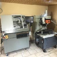
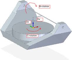
maybe you can point me straight to the right kins - I have a 5 axis machine coming in typical tool room fashin, and tilting a axis on table and tilting b axis on spindle, just like the picture attached. Is there a working kinematics already for this type?
Regards
Daniel
maybe you can point me straight to the right kins - I have a 5 axis machine coming in typical tool room fashin, and tilting a axis on table and tilting b axis on spindle, just like the picture attached. Is there a working kinematics already for this type?
Regards
Daniel
Please Log in or Create an account to join the conversation.
- Aciera
-

- Offline
- Administrator
-

Less
More
- Posts: 4617
- Thank you received: 2043
30 Dec 2021 19:46 #230356
by Aciera
Replied by Aciera on topic TCP 5-axis kinematics
As far as I'm aware there isn't one for that particular kinematic setup. yet.
linuxcnc.org/docs/html/motion/5-axis-kinematics.html
So this might be a good opportunity for you to make a lasting contribution...
linuxcnc.org/docs/html/motion/5-axis-kinematics.html
So this might be a good opportunity for you to make a lasting contribution...
Please Log in or Create an account to join the conversation.
- jess
- Offline
- New Member
-

Less
More
- Posts: 10
- Thank you received: 1
05 Jan 2022 05:50 #230829
by jess
Replied by jess on topic TCP 5-axis kinematics
Thanks for this post, I think I have successfully run the 5-axis kinematics with LinuxCNCBut I don't have a matching post-processing file, and I don't know much about post-processingI would like to know, is there any relevant 5-axis CAM post-processing for reference? For example about Mastercam or UG
Please Log in or Create an account to join the conversation.
- Micromachining
- Offline
- New Member
-

Less
More
- Posts: 10
- Thank you received: 2
10 Jan 2022 15:41 #231313
by Micromachining
Replied by Micromachining on topic TCP 5-axis kinematics
I wonder if PocketNC will release its new Kinetic control too the public domain its Full TCP and is based on Linuxcnc. so I'm sure they would share something and has full post-processer support for the big names.
Please Log in or Create an account to join the conversation.
- mydani
-

- Offline
- Premium Member
-

Less
More
- Posts: 100
- Thank you received: 9
12 Jan 2022 06:25 #231531
by mydani
Replied by mydani on topic TCP 5-axis kinematics
If it's based on Linuxcnc, shouldn't some license apply so they have to open up the code base when asked?
Please Log in or Create an account to join the conversation.
- jsskangas
- Offline
- Premium Member
-

Less
More
- Posts: 144
- Thank you received: 8
16 Jan 2022 13:11 - 16 Jan 2022 13:12 #232011
by jsskangas
Replied by jsskangas on topic TCP 5-axis kinematics
hello
Finally I have need or forced to upgrade my setup to switchkin functionality.
I installed Buster and 2.8 version and updated to newest 2.9 pre0 5518.
Few notes why I need compile my own kinematic and why I can not use supplied ones.
XYZBC kinematics are still wrong, C axis rotates correctly, but B axis rotates wrong direction .
Second reason is I updated my mill with A axis, I run now 6 axis setup.
Nikken ax120 for BC axis and Detlev Hoffman as A axis.
So I need to change between 3 different kinematics, 1: linear, 2: XYZBC and 3: XYZA.
There is few question from how switchkin works.
M428, M429, M430 are routed to subprograms which two main function are
change kinematic mode and sync new position.
M68 command is used to control analog output pin which is then used to indicate kinematic mode.
M66 used sync new position to system
I use following lines in HAL to connect this analog pin to my kinematics
net :kinstype-select <= motion.analog-out-03
net :kinstype-select => motion.switchkins-type
net :kinstype-select => XYZABCsmkins.wmode
Where is motion.switchkins-type connected and do we need it and if, why (as M66 does sync)?
Last edit: 16 Jan 2022 13:12 by jsskangas.
Please Log in or Create an account to join the conversation.
- Aciera
-

- Offline
- Administrator
-

Less
More
- Posts: 4617
- Thank you received: 2043
16 Jan 2022 15:13 - 16 Jan 2022 15:20 #232021
by Aciera
Replied by Aciera on topic TCP 5-axis kinematics
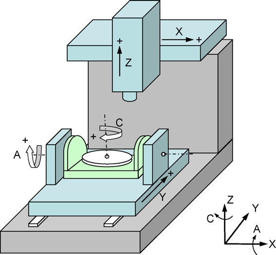
"XYZBC kinematics are still wrong, C axis rotates correctly, but B axis rotates wrong direction ."
I'm fairly sure that xyzbc-trt kinematics follows this convention, which seems correct to me:
"Where is motion.switchkins-type connected and do we need it and if, why (as M66 does sync)?"
For custom kinematics it is recommended to use the "userkins.comp" template:
linuxcnc.org/docs/html/man/man9/userkins.9.html
For an example you could have a look at the "millkins" simulation config that uses "millturn.comp" found at
src/hal/components where you will also find the above mentioned "userkins.comp". Comparing the two should give you a good idea how things work. For three kinematics you basically have to expand the case structure in the .comp and add the required forward and backward kinematic model. "switchkins_type" will then select the required kinematic model. So you would need to expand this with a "case 2":
// create case structure for switchable kinematics
switch (switchkins_type) {
case 0: rtapi_print_msg(RTAPI_MSG_INFO,
"kinematicsSwitch:TYPE0\n");
*haldata->kinstype_is_0 = 1;
*haldata->kinstype_is_1 = 0;
break;
case 1: rtapi_print_msg(RTAPI_MSG_INFO,
"kinematicsSwitch:TYPE1\n");
*haldata->kinstype_is_0 = 0;
*haldata->kinstype_is_1 = 1;
break;
default: rtapi_print_msg(RTAPI_MSG_ERR,
"kinematicsSwitch:BAD VALUE <%d>\n",
switchkins_type);
*haldata->kinstype_is_1 = 0;
*haldata->kinstype_is_0 = 0;
return -1; // FAIL }
And then add the kinematic model further down in the int "kinematicsForward(" and the "int kinematicsInverse("-sections of the code.
Attachments:
Last edit: 16 Jan 2022 15:20 by Aciera.
Please Log in or Create an account to join the conversation.
- jsskangas
- Offline
- Premium Member
-

Less
More
- Posts: 144
- Thank you received: 8
16 Jan 2022 15:32 - 16 Jan 2022 15:35 #232022
by jsskangas
Replied by jsskangas on topic TCP 5-axis kinematics
I was wrong both of those axis B and C rotates wrong direction.
" I'm fairly sure that xyzbc-trt kinematics follows this convention, which seems correct to me: "
Well, I have build (calculated and coded) machine tool kinematics and postprocessor as a professional for past 10 years for Siemens NX.
So I am pretty sure that B/axis rotation is wrong in that example.
if it is not wrong then Mazak, Grob, Index, Okuma, Doosan, Siemens, roeders, Soraluce, GF, DMG and plus some other manufactures has understood rotation direction of machine axis completely wrong, but I doubt it.
Last edit: 16 Jan 2022 15:35 by jsskangas.
Please Log in or Create an account to join the conversation.
- Aciera
-

- Offline
- Administrator
-

Less
More
- Posts: 4617
- Thank you received: 2043
16 Jan 2022 15:50 - 16 Jan 2022 16:26 #232023
by Aciera
Replied by Aciera on topic TCP 5-axis kinematics
I don't have experience with 5-axis machining so I really have no idea but if the c-axis rotation follows the "right-hand" rule to define positive rotation direction then why would b-axis suddenly be opposite?
This seems to be in agreement with the current definition:
www.isg-stuttgart.de/kernel-html5/en-GB/296412555.html
Can you maybe provide more information as to the theory of how this is supposed to work?
[edit]
I found this xyzac setup with a and c supposedly rotating in the opposite direction:
As I said I have really no idea so maybe somebody could provide more insight.
Attachments:
Last edit: 16 Jan 2022 16:26 by Aciera.
Please Log in or Create an account to join the conversation.
- jsskangas
- Offline
- Premium Member
-

Less
More
- Posts: 144
- Thank you received: 8
16 Jan 2022 17:04 - 16 Jan 2022 17:44 #232027
by jsskangas
Replied by jsskangas on topic TCP 5-axis kinematics
Ok
Basic idea is that we always program tool movement against part(G54 coordinate offset example).
Lets start with linear axis it is easy to explain.
When we program NC-code example X10.0, this means that tool is now in position X=10.0
Now if this X-axis moves tool, to get tool in to X10.0 position,
axis needs to move positive direction of X axis of G54 coordinate system.
In case of part is moved (table) it need to move negative direction to get tool in X10.0 position.
Same rule applies to rotation:
If tool is rotated, we use right hand rule.
If part is rotated we use left hand rule.
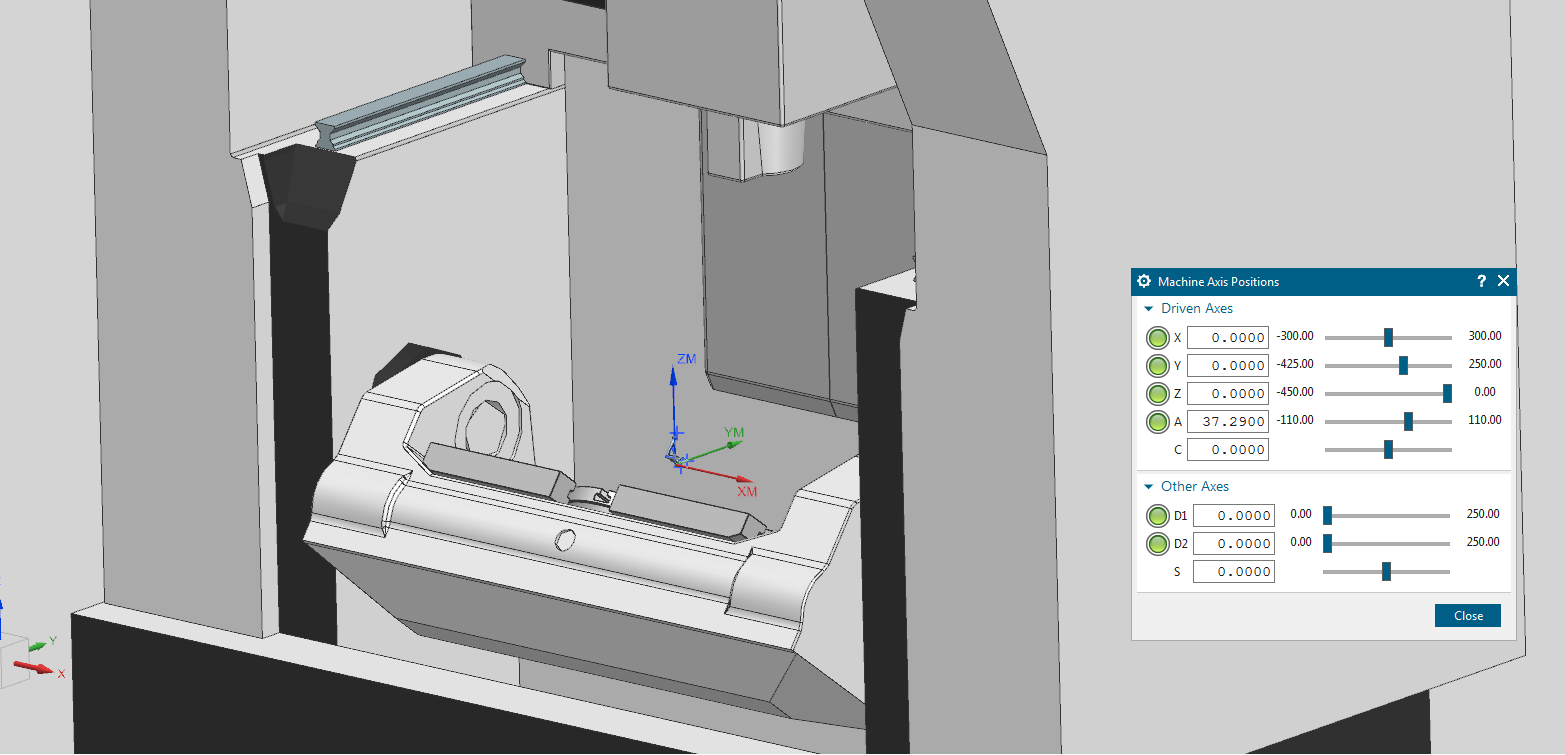
Lets take this A-axis from above machine, when we look along X-axis (not againt it), tool positive rotation is CW (right hand rule for rotating tool).
So if we command A30.0 tool needs to rotate Clock Wise 30 degree to achieve this position.
But again if we move part it needs to rotate CCW so that tool will achieve A30. position (Left hand rule for rotating part).
Attachments:
Last edit: 16 Jan 2022 17:44 by jsskangas.
Please Log in or Create an account to join the conversation.
Time to create page: 0.201 seconds


