

Dual PID loops with motor encoder + scale encoder per axis

More
2 years 6 months ago #298234 by tommylight
Simple explanation would be:
Torque mode = no tacho generator on the motor
Velocity mode = tacho on motor and wired to drive, not wired to control
Position mode = all of those with encoder wired to control
-
Quite a while back i read here somewhere that LinuxCNC can output tacho signal from encoder feedback using some type of DAC converter for drives in velocity mode and using motors without tacho. Not important for this situation.
From the pictures it looks there is no tacho on the motor, so torque mode, and since LinuxCNC can use them with just encoder feedback and a single PID loop, should be easy to make it work, but tuning might be a challenge.
Since you also have linear scales (i hope i am on the right topic), having two loops should be much better, so use motor encoder to close velocity loop in LinuxCNC with the first PID, and use the scales to close the position loop in LinuxCNC with the second PID.
Should be doable, but i have yet to try as i have no linear scales on anything.
The following user(s) said Thank You: TangentAudio

Please Log in or Create an account to join the conversation.

More
2 years 6 months ago #298241 by TangentAudio
Thanks Tommy,

By your logic, these are probably torque mode drives after all? There is a quadrature encoder on the motors, but no tachometer/generator that would produce an analog output relative to velocity. I was conflating tachometers and encoders, since you could use an encoder to infer velocity and it would act as a tacho in theory. That's my lack of servo experience showing.

I might set up a DMM to read voltage across the motor and record voltages as I step through a series of open loop PWM control values across the full scale range. I could do another run and measure current as well. Might be even better to do it with a large load resistor (or a DC load) since that would eliminate the back EMF from the motor influencing the reading?

At least then it should be apparent whether voltage or current is changed proportionally to the control input and I could convince myself what sort of drives I have !image missing /media/kunena/emoticons/smile.png
.

Please Log in or Create an account to join the conversation.

More
2 years 6 months ago #298247 by TangentAudio
A little bench experiment running the motor open loop with no load across 0%-100% PWM values.  

Except for the discontinuity at the bottom, voltage looks more linear to me, though they both look reasonably linear.  image missing /media/kunena/emoticons/unsure.png  Maybe loading the motor would make it more clear, but I have to find a good way to do that on the bench.


Please Log in or Create an account to join the conversation.
More
2 years 6 months ago - 2 years 6 months ago #298258 by TangentAudio
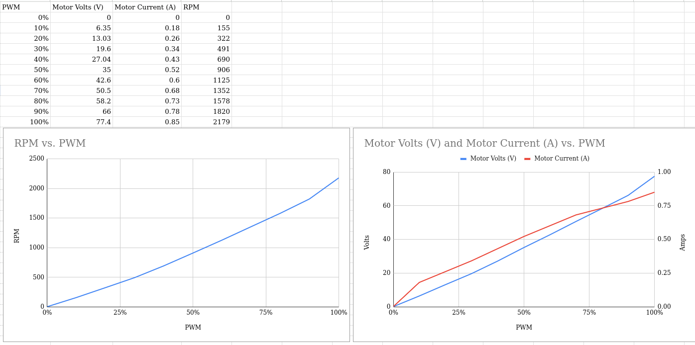
Another test with cleaner results.  One of my DMMs had a low battery so it was having some trouble auto-ranging I think, so the last results were a bit screwy.  I also measured RPM with my optical tach this time.

Another observation: when I run the motor at a fixed PWM value and apply a physical load to the motor, current will jump up substantially but the voltage will drop a much smaller amount percentage-wise.  So it behaves more like a CV power supply and not a CC power supply.  The voltage drop could be explained by the 10ft long 16 gauge wire that feeds the motor.


Last edit: 2 years 6 months ago by TangentAudio.

Please Log in or Create an account to join the conversation.

More
2 years 6 months ago #298508 by TangentAudio
I am speculating these may just be plain H bridge drives.

An apparent quote from PCW, found at the very bottom of wiki.linuxcnc.org/cgi-bin/wiki.pl?Servo_Tuning_Detail_How_To

Bare H-bridge drives running PM DC motors behave somewhat like velocity mode servos
(with quite low velocity feedback gain) So they end up being somewhere between velocity
and torque mode.
That is, you are setting the average motor drive voltage with the PWM value. This sets the
approximate motor velocity because the motor will accelerate to a velocity where the generated
back EMF is close to the supplied voltage. If the motor impedance was zero, you would have close
to a perfect velocity mode servo, but the impedance is substantial which leads to the low
inherent feedback gain.

Normally for Hbridges, I would start with a low P value and tune the D term as high as
possible without excessive buzzyness, then set FF1 so that the actual position does
not lead or lag the commanded position at full speed, then I would tune FF2 so that
the actual position does not lead or lag the commanded position during acceleration
Then I would tune P as high as possible without oscillation, overshoot and then when
everything else is close, add as much I term as possible without instability.

The following user(s) said Thank You: tommylight

Please Log in or Create an account to join the conversation.

More
2 years 6 months ago - 2 years 6 months ago #298534 by Tinine
In velocity-mode, the drive is a rate-device where the command signal dictates the RPM of the motor. Remove the command and the motor stops dead and the shaft can't be rotated by hand.

In Torque-mode, the command dictates the amount of current applied to the motor. Remove the command and the motor will coast to a stop and then the shaft can be easily rotated by hand, as if the drive was dis-abled.
Last edit: 2 years 6 months ago by Tinine.
The following user(s) said Thank You: TangentAudio

Please Log in or Create an account to join the conversation.

Time to create page: 0.138 seconds
Powered by Kunena Forum