
- Posts: 711
- Thank you received: 9
Replacing Advanced Motion Controls "brush type 12A8 with "Axcent" amplifier
- new2linux
- Offline
- Platinum Member
-

Less
More
6 years 2 weeks ago - 6 years 2 weeks ago #186094
by new2linux
Todd, Thanks for your help. I have reviewed my emails with A-M-C techs; this is a response from an earlier question.
This is the email:
"2.6.4 Encoder Velocity Mode In Encoder Velocity Mode, the input command controls the motor
velocity, with the frequency of the encoder pulses closing the velocity loop. An analog velocity
monitor output allows observation of the actual motor speed through a kHz/V scaling factor
found on the drive datasheet. The voltage value read at the velocity monitor output can
be used to determine the motor RPM through the scaling factor. See “Velocity Monitor Output” on
page 41 for the motor RPM equation.
Note
The high resolution of motor mounted encoders allows for excellent
velocity control and smooth motion at all speeds. Encoder Velocity
Mode should be used for applications requiring precise and accurate
velocity control, and is especially useful
I also read this:
2.5.2 Incremental Encoder
Analog servo drives that use encoder feedback utilize two single-ended
or differential incremental encoder inputs for velocity control. The encoder provides
incremental position feedback that can be extrapolated into very precise velocity
information. The encoder signals are read as "pulses" that the drive uses to essentially keep track of
the motor’s position and direction of rotation. Based on the speed and order in which these pulses
It seems to me I need "two single-ended" or "differential incremental
encoder" inputs for velocity control."
This is response from A-M-C:
"The AB15A100 only accepts a single ended encoder input. If you do have a differential encoder, you can just use the A+ and B+ lines and don't connect the /A and /B signals. It will still work as a single ended signal, you just won't have the benefits of a differential signal."
The manual is too large to attach. Edit: To have access to the A-M-C manuals you need password.
2nd Edit: I have approached AMC with the hope of an explanation and this is the response: If you have a differential encoder you only need to connect the A+ and B+ signals and it will work just fine.
It appears both will work. I am not shore of some of the following that is required to order encoder.
The pin out
The power supply voltage to the encoder (this is 5 VDC)
The signal output type from the encoder
The signal out voltage level from the encoder
The resolution or CPR of the encoder (2000)
many thanks!
Replied by new2linux on topic Replacing Advanced Motion Controls "brush type 12A8 with "Axcent" amplifier
Todd Zuercher wrote: This is to add encoder feedback to the drive so it can operate in velocity mode. The encoder can be used for both the position feedback to Linuxcnc and the velocity feedback to the drive (if you connect it to both).
Todd, Thanks for your help. I have reviewed my emails with A-M-C techs; this is a response from an earlier question.
This is the email:
"2.6.4 Encoder Velocity Mode In Encoder Velocity Mode, the input command controls the motor
velocity, with the frequency of the encoder pulses closing the velocity loop. An analog velocity
monitor output allows observation of the actual motor speed through a kHz/V scaling factor
found on the drive datasheet. The voltage value read at the velocity monitor output can
be used to determine the motor RPM through the scaling factor. See “Velocity Monitor Output” on
page 41 for the motor RPM equation.
Note
The high resolution of motor mounted encoders allows for excellent
velocity control and smooth motion at all speeds. Encoder Velocity
Mode should be used for applications requiring precise and accurate
velocity control, and is especially useful
I also read this:
2.5.2 Incremental Encoder
Analog servo drives that use encoder feedback utilize two single-ended
or differential incremental encoder inputs for velocity control. The encoder provides
incremental position feedback that can be extrapolated into very precise velocity
information. The encoder signals are read as "pulses" that the drive uses to essentially keep track of
the motor’s position and direction of rotation. Based on the speed and order in which these pulses
It seems to me I need "two single-ended" or "differential incremental
encoder" inputs for velocity control."
This is response from A-M-C:
"The AB15A100 only accepts a single ended encoder input. If you do have a differential encoder, you can just use the A+ and B+ lines and don't connect the /A and /B signals. It will still work as a single ended signal, you just won't have the benefits of a differential signal."
The manual is too large to attach. Edit: To have access to the A-M-C manuals you need password.
2nd Edit: I have approached AMC with the hope of an explanation and this is the response: If you have a differential encoder you only need to connect the A+ and B+ signals and it will work just fine.
It appears both will work. I am not shore of some of the following that is required to order encoder.
The pin out
The power supply voltage to the encoder (this is 5 VDC)
The signal output type from the encoder
The signal out voltage level from the encoder
The resolution or CPR of the encoder (2000)
many thanks!
Last edit: 6 years 2 weeks ago by new2linux. Reason: password for manuals 2nd Edit:amc responce
Please Log in or Create an account to join the conversation.
- new2linux
- Offline
- Platinum Member
-
Less
More
- Posts: 711
- Thank you received: 9
6 years 1 week ago - 5 years 11 months ago #186599
by new2linux
Replied by new2linux on topic Replacing Advanced Motion Controls "brush type 12A8 with "Axcent" amplifier
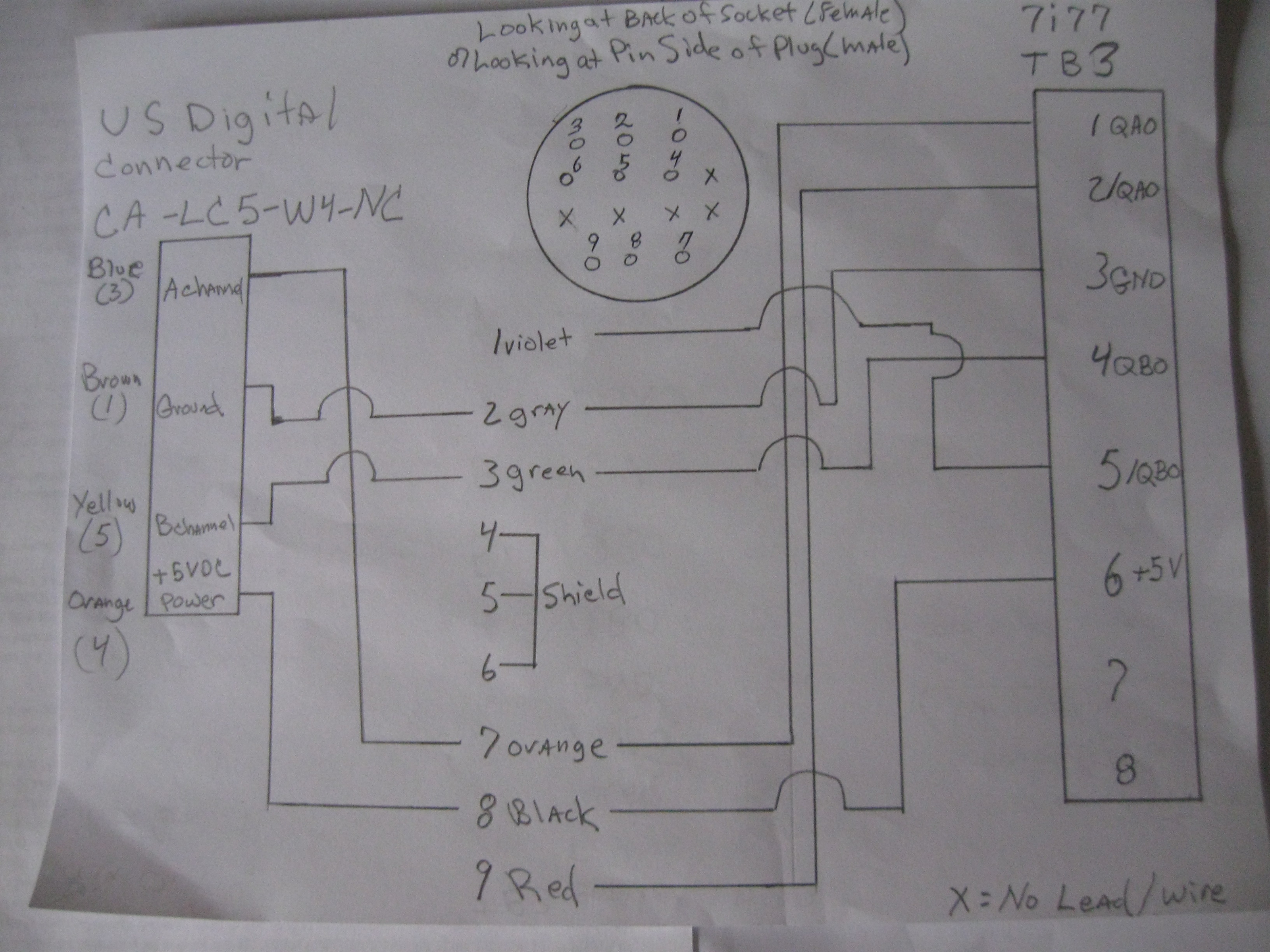
I offer my many thanks to all of those people who make this forum work so well. I have reviewed several documents including the 7i77 manual. As per the manual and the tech at USDigital this diagram I believe is accurate to fit the application. The jumpers on 7i77 are moved to the left, which means board is configured to receive a single ended encoder signal (based on page 3 of the 7177 manual. I believe the motor listed at this prior post: (27 Sep 2020 15:11 - 28 Sep 2020 16:07 #18398) requires encoders described below to work property.
EM1-2-500-N
HUBDISK-2-500-500-NE
CA-LC5-W4-NC-1
You can find mechanical drawings and pricing for each item on our website here:
encoder:
www.usdigital.com/products/encoders/incr.../modules/EM1-2-500-N
encoder wheel:
www.usdigital.com/products/encoders/incr...HUBDISK-2-500-500-NE
Cable&Connector
www.usdigital.com/products/accessories/cables/CA-LC5-W4-NC-1
The diagram shows the 7I77 (TB3) on the right side, going to the original prototrak plug (the round plug, numbered 1 to 9) and the USDigital CA-LC5-W4-NC-1 to the left side of screen.
Many thanks,
Edit: The new (USDigital) encoders are installed. Jumper set to the left on TB3. The DRO does not function. What should I be looking for? Status LEDs look correct.
All help is warmly welcomed.
EM1-2-500-N
HUBDISK-2-500-500-NE
CA-LC5-W4-NC-1
You can find mechanical drawings and pricing for each item on our website here:
encoder:
www.usdigital.com/products/encoders/incr.../modules/EM1-2-500-N
encoder wheel:
www.usdigital.com/products/encoders/incr...HUBDISK-2-500-500-NE
Cable&Connector
www.usdigital.com/products/accessories/cables/CA-LC5-W4-NC-1
The diagram shows the 7I77 (TB3) on the right side, going to the original prototrak plug (the round plug, numbered 1 to 9) and the USDigital CA-LC5-W4-NC-1 to the left side of screen.
Many thanks,
Edit: The new (USDigital) encoders are installed. Jumper set to the left on TB3. The DRO does not function. What should I be looking for? Status LEDs look correct.
All help is warmly welcomed.
Last edit: 5 years 11 months ago by new2linux. Reason: typo: 2nd edit; detailed diagram: edit01 correct encoder wheel hole size
Please Log in or Create an account to join the conversation.
- new2linux
- Offline
- Platinum Member
-
Less
More
- Posts: 711
- Thank you received: 9
6 years 4 days ago #187473
by new2linux
Replied by new2linux on topic Replacing Advanced Motion Controls "brush type 12A8 with "Axcent" amplifier
My question goes out to all, what is the encoder channel? I have read the 7i77 manual, have I missed the area to read? What is the "encoder channel" ? My question is related to setting the hal scope to see the "square wave" produced by the encoder count? Need to prove the encoders are working.
all help warmly welcomed
many thanks!
all help warmly welcomed
many thanks!
Please Log in or Create an account to join the conversation.
- Todd Zuercher
- Offline
- Platinum Member
-
Less
More
- Posts: 4793
- Thank you received: 1480
6 years 4 days ago #187555
by Todd Zuercher
Replied by Todd Zuercher on topic Replacing Advanced Motion Controls "brush type 12A8 with "Axcent" amplifier
As to the exact definition of that phrase, it is a little hard to say without the context of the text you are referring to.
But to get to the root of your real question. In Halscope you will want to look at the hal pins "hm2_5i25.0.encoder.nn.input-a" and "hm2_5i25.0.encoder.nn.input-b" (replacing nn with the number of the encoder input you want to use such as 00,01,02...)
PS: Remember Halscope can only sample these signals at the the servo thread rate. So try not to turn the encoder at a rate that might output pulses faster than about 500/sec, or you will get misleading results.
The following user(s) said Thank You: new2linux
Please Log in or Create an account to join the conversation.
- new2linux
- Offline
- Platinum Member
-
Less
More
- Posts: 711
- Thank you received: 9
6 years 4 days ago #187569
by new2linux
Replied by new2linux on topic Replacing Advanced Motion Controls "brush type 12A8 with "Axcent" amplifier
Todd, Many, many thanks for your help. I have used the pin selection you suggested, no motion or change of any kind. No DRO. Through process of elimination, the last component is the 7i77 card. To edit this to accept a different encoder at different location like TB4 (encoder 03 & 04). Is this how I should be thinking about this?
Please Log in or Create an account to join the conversation.
- Todd Zuercher
- Offline
- Platinum Member
-
Less
More
- Posts: 4793
- Thank you received: 1480
6 years 4 days ago #187570
by Todd Zuercher
Replied by Todd Zuercher on topic Replacing Advanced Motion Controls "brush type 12A8 with "Axcent" amplifier
I don't understand, earlier in this thread you posted plots that obviously showed that you had the encoder connected to the 7i77 and DRO feedback working in Linuxcnc. What changed? You should not have removed any of the encoder wiring to the 7i77 card. We only suggested adding wires from the A and B terminals of the 7i77 to the encoder A and B terminals of the servo drive, to enable Velocity control of the drive and make tuning them easier.
The following user(s) said Thank You: new2linux
Please Log in or Create an account to join the conversation.
Time to create page: 1.685 seconds