Optimum Optimill MH50V CNC conversion
- Unlogic
- Offline
- Elite Member
-

- Posts: 240
- Thank you received: 120
But being a rookie I don't really have a good reference here. What would be a suitable number of steps per revolution for a setup like mine with 5mm pitch ball screws driven with a 1:2 reduction using 750w servos.
I've currently set it 1000 steps per revolution but maybe that's a bit too crude?
Please Log in or Create an account to join the conversation.
- PCW
-

- Offline
- Moderator
-

- Posts: 17985
- Thank you received: 5278
I would chose a number around 10x higher
Please Log in or Create an account to join the conversation.
- Unlogic
- Offline
- Elite Member
-
- Posts: 240
- Thank you received: 120
Please Log in or Create an account to join the conversation.
- Unlogic
- Offline
- Elite Member
-
- Posts: 240
- Thank you received: 120
Based on the feedback from PCW I reconfigured the servo drives and updated my INI file so that I now have 10000 steps per revolution of the servo drives and it really made things noticeable smoother which I had not expected.1000 steps per turn is 5u per step which is pretty crude
I would chose a number around 10x higher
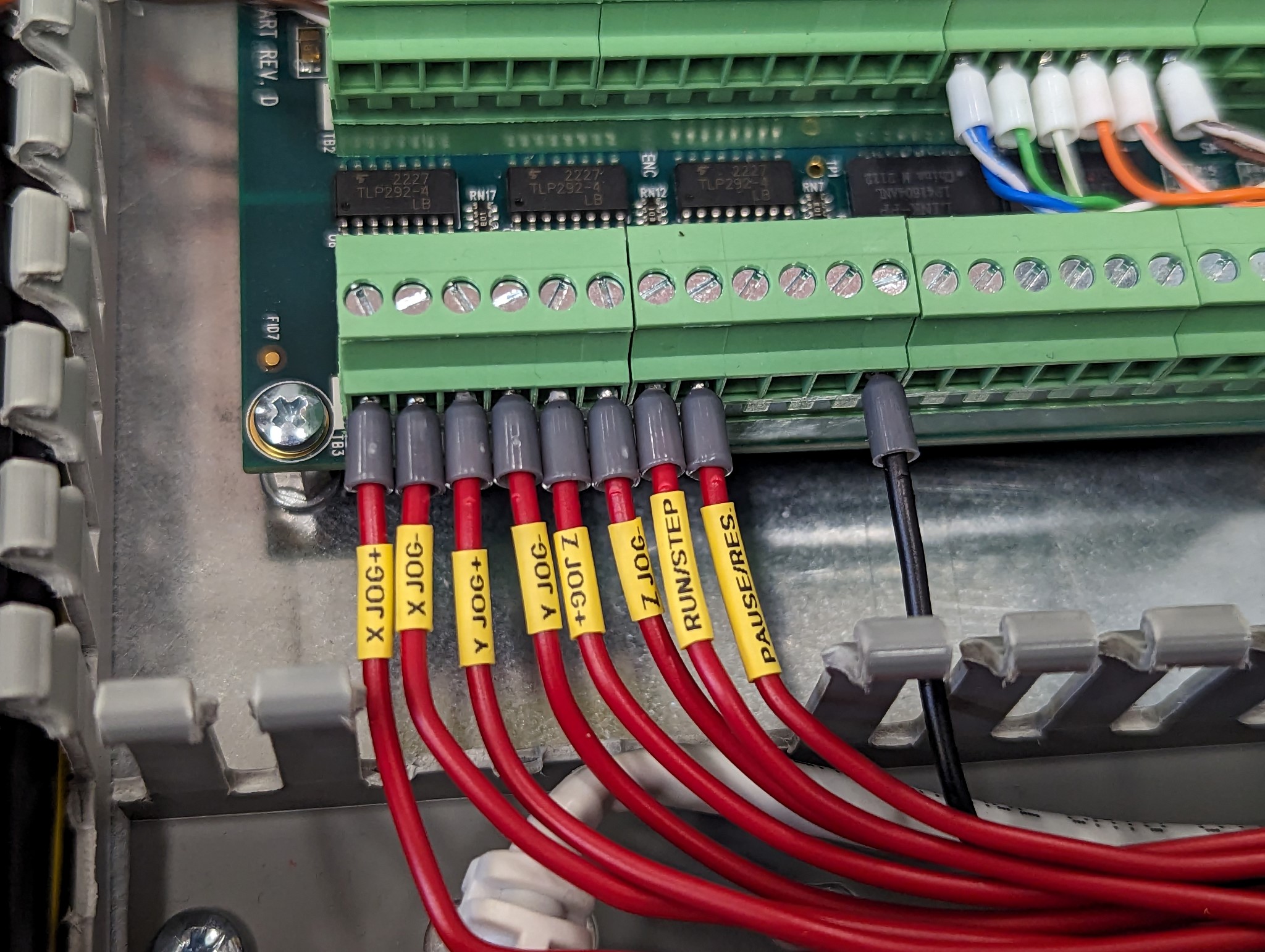
Next up worked on the fault handling where I have wired up both the servo ready (SRDY) and alarm (ALRM) signals to inputs on the 7i84.
However I realized now that the servo ready signal is most likely redundant as the servo ready and alarm pins are essentially the same signal inverted. My thought here was that the alarm signal was active high which would mean that if the circuit breaker to the servo drive triggered I wouldn't get any fault. But it turned out that the alarm signal is actually active low so if the power is cut LinuxCNC triggers a fault anyway.
So in the end all I had to add to my custom.hal was the following three lines:
#Servo drive fault handling
net x-drive-fault => joint.0.amp-fault-in <= hm2_7i96s.0.7i84.0.0.input-16-not
net y-drive-fault => joint.1.amp-fault-in <= hm2_7i96s.0.7i84.0.0.input-17-not
net z-drive-fault => joint.2.amp-fault-in <= hm2_7i96s.0.7i84.0.0.input-18-not
After that I turned my attention to the alarm reset (ARST) signal from the Mesa 7i84 to the drives so that I can clear any fault codes on the drives without power cycling the whole control cabinet. I ended up just piggybacking the reset signal to the oneshot of the e-stop reset signal already resent in custom.hal file. So if there is a fault LinuxCNC stops and I can easily clear the codes by just triggering and resetting the e-stop. The parts in bold in snippet below is what I added to the HAL file.
With e-stop, steps and alarms sorted I became a little more confident in starting to push the servos a bit so I hooked up the physical buttons for jogging, run/step, pause/resume.loadrt estop_latch
loadrt oneshot count=2
addf estop-latch.0 servo-thread
addf oneshot.0 servo-thread
addf oneshot.1 servo-thread
setp oneshot.0.width 1
setp oneshot.1.width 1
#Automatically reset e-stop in UI and any fault codes on the drives
net reset-trig oneshot.0.in <= hm2_7i96s.0.7i84.0.0.input-00
net reset-ui oneshot.0.out => halui.estop.reset hm2_7i96s.0.7i84.0.0.output-11 hm2_7i96s.0.7i84.0.0.output-12 hm2_7i96s.0.7i84.0.0.output-13
#Latching e-stop function
net estop-loopout iocontrol.0.emc-enable-in <= estop-latch.0.ok-out
net estop-loopin iocontrol.0.user-enable-out => estop-latch.0.ok-in
net estop-reset iocontrol.0.user-request-enable => estop-latch.0.reset
net remote-estop estop-latch.0.fault-in <= hm2_7i96s.0.7i84.0.0.input-00-not
#When software e-stop is detected momentarily break e-stop circuit to trigger safety relay requiring external reset
net relay-in oneshot.1.in <= estop-latch.0.fault-out
net relayout oneshot.1.out-not => hm2_7i96s.0.7i84.0.0.output-00
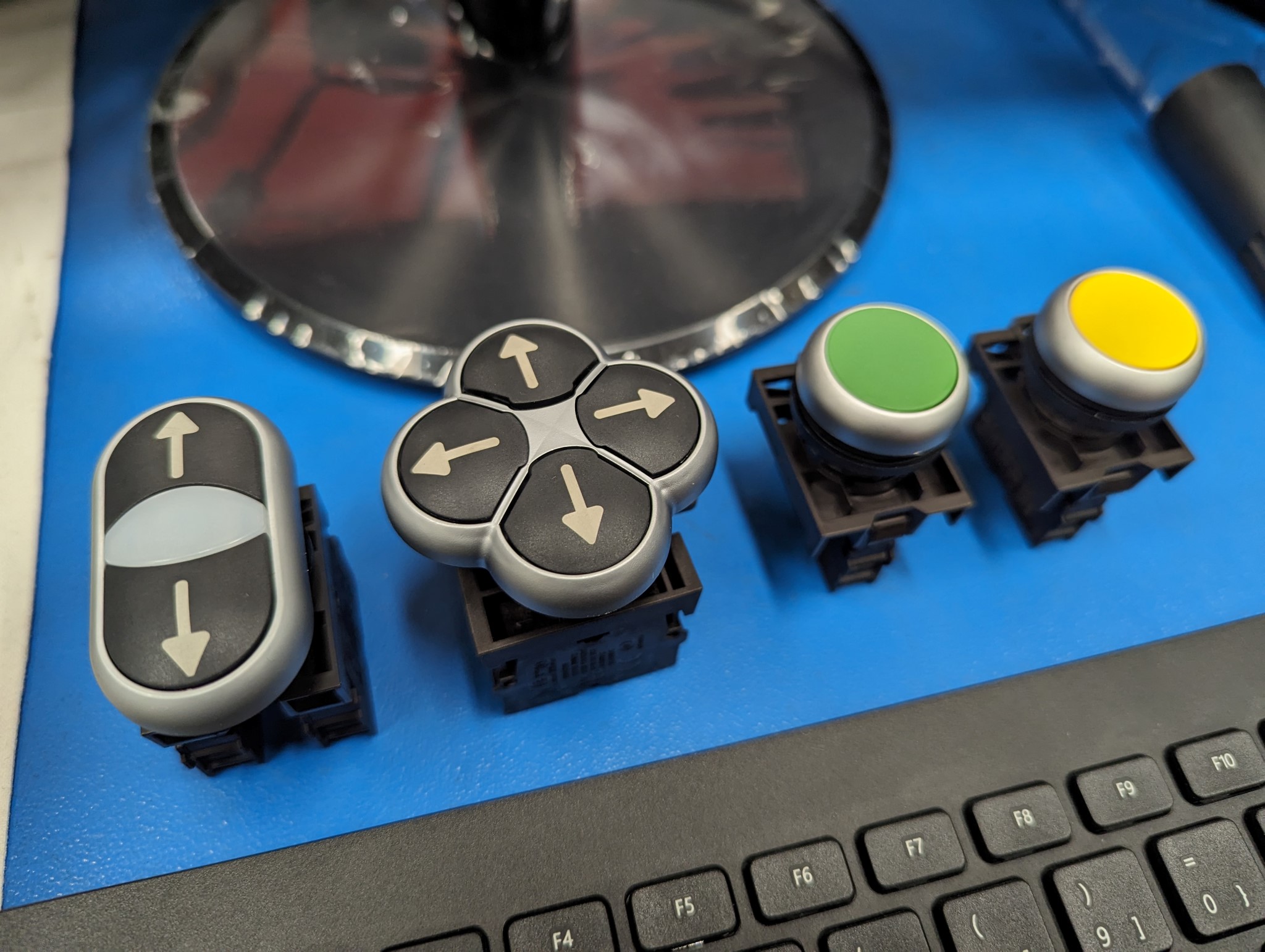
It was at this time that I found the setting on the Dymo machine for font size allowing me to create much smaller heat shrink labels

Getting the run/step, pause/resume to work using the HAL code provided by BigJohnT here was a breeze and worked on the first attempt. Big thanks to John for that code as it would have taken me a considerable amount of time to write it from scratch. In order to keep my custom.hal file as readable as possible I opted to put John's code in a separate run_pause.hal file which I then included in my custom.hal file using the below.
source run_pause.hal
The jogging however proved a little bit more tricky. I had the HAL pins set correctly and I could see the inputs and HAL pins being triggered but there was no movement of the servos when I pressed the buttons. I read that the halui.axis.X.plus/halui.axis.X.minus pins only worked after the machine had been homed but homing didn't help either. After a bit more reading and I found out that the jog speed and increment in the GUI is separate from the physical jog buttons (which makes sense for those with physical jog speed select switches) so setting the parameter below was required to get things moving.
I found a code example here on the forum by Nebur for synchronizing the physical jog speed with the setting in the Axis GUI. My plan is to use Probe Basic so I hope something similar can realized for the GUI too. If anyone has any input here it would be much appreciatedsetp halui.axis.jog-speed 100

Attachments:
Please Log in or Create an account to join the conversation.
- tommylight
-

- Offline
- Moderator
-
- Posts: 21734
- Thank you received: 7425
Most of what i used did, so i never needed to add anything except the fault inputs.
Fault input should disable the machine by disabling drives so all that it required to clear was to press F2/enable and move on.
Please Log in or Create an account to join the conversation.
- Unlogic
- Offline
- Elite Member
-
- Posts: 240
- Thank you received: 120
As the servo drives have dual power inputs the fault codes are retained even when e-stop is triggered and reset because the logic section remains powered during an e-stop.
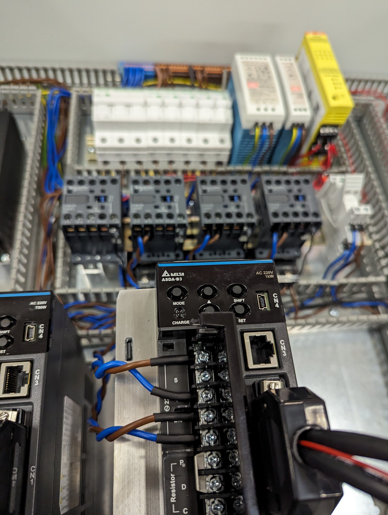
Here is snippet from Delta manual on how they want the drives to be wired up:
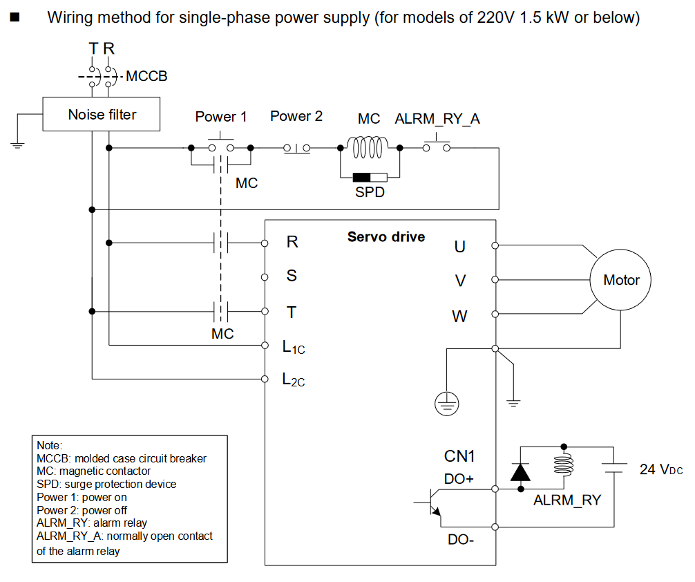
So I've wired mine up according to the manual with the both inputs going through curcuit breaker and EMI filter but only the upper input goes through the contactor.
This way the step/position from the encoders is retained in the drives during e-stop which hopefully means that homing won't always be required after an e-stop.
Attachments:
Please Log in or Create an account to join the conversation.
- anders
- Offline
- New Member
-

- Posts: 2
- Thank you received: 1
Please Log in or Create an account to join the conversation.
- Unlogic
- Offline
- Elite Member
-
- Posts: 240
- Thank you received: 120
I'm using a DYMO Rhino 4200 together with this non genuine heat shrink tube from Amazon ( link ) and a cheap 9V AC/DC adapter also from Amazon ( link ) so that I don't have to deal with batteries.
If you buy one of these units, don't forget to turn down the font size like I did initially
Please Log in or Create an account to join the conversation.
- Unlogic
- Offline
- Elite Member
-
- Posts: 240
- Thank you received: 120
I made short video showing how the drivers retain the current step count when they are wired up like it's described in the manual from Delta.Do the drives clear faults when disabled and enabled again?
Most of what i used did, so i never needed to add anything except the fault inputs.
Fault input should disable the machine by disabling drives so all that it required to clear was to press F2/enable and move on.
Please Log in or Create an account to join the conversation.
- tommylight
-
- Offline
- Moderator
-
- Posts: 21734
- Thank you received: 7425
Thank you.
Please Log in or Create an account to join the conversation.