Optimum Optimill MH50V CNC conversion
- Unlogic
- Offline
- Elite Member
-

Less
More
- Posts: 240
- Thank you received: 120
10 Sep 2024 10:49 #309827
by Unlogic
Replied by Unlogic on topic Optimum Optimill MH50V CNC conversion
With all the parts manufactured it was time for the scary bit, taking apart the gearbox and removing all the parts that will no longer be needed.
First thing to be removed was the huge 2kw induction motor.

Next up was the top cover for the gearbox which to to my great delightment had two threaded holes where long bolts could be inserted to gently lift the cover.

Getting the cover off and removing all the gears however was a bit tricky as the gears and gear change mechanism had to be removed in a particular way in order to not get all tangled up.


Here is a test fit of the servo mount on the top cover of the gearbox.
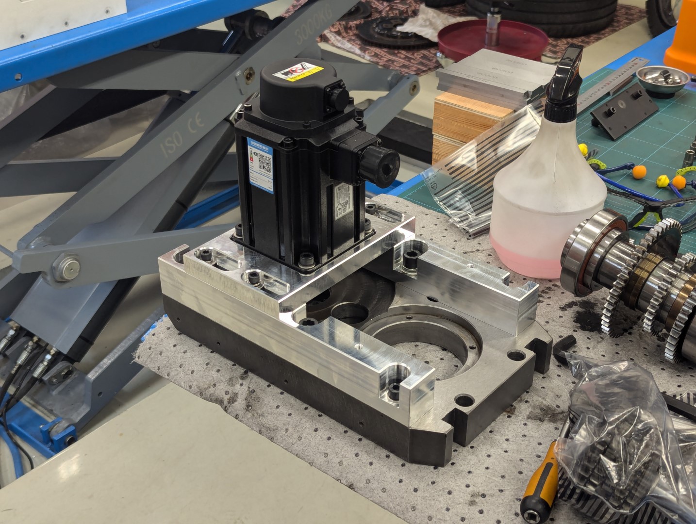
After verifying that the mount actually fit I removed two of the three shaft in the gearbox. On the final shaft I pressed off all the gears that could be removed from it and installed new steel caged SKF bearing rated for 12k+ RPM


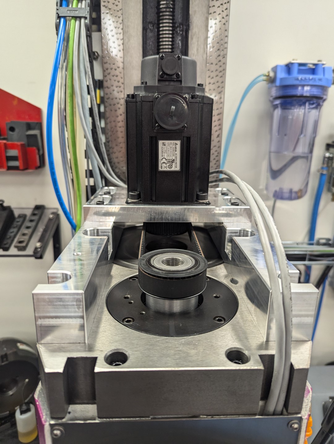
Here is how the shaft looks with the pulley adapter on top (just loosely installed at this time).

First thing to be removed was the huge 2kw induction motor.
Next up was the top cover for the gearbox which to to my great delightment had two threaded holes where long bolts could be inserted to gently lift the cover.
Getting the cover off and removing all the gears however was a bit tricky as the gears and gear change mechanism had to be removed in a particular way in order to not get all tangled up.
Here is a test fit of the servo mount on the top cover of the gearbox.
After verifying that the mount actually fit I removed two of the three shaft in the gearbox. On the final shaft I pressed off all the gears that could be removed from it and installed new steel caged SKF bearing rated for 12k+ RPM
Here is how the shaft looks with the pulley adapter on top (just loosely installed at this time).
Attachments:
The following user(s) said Thank You: besriworld
Please Log in or Create an account to join the conversation.
- Unlogic
- Offline
- Elite Member
-
Less
More
- Posts: 240
- Thank you received: 120
10 Sep 2024 11:09 #309829
by Unlogic
Replied by Unlogic on topic Optimum Optimill MH50V CNC conversion
With the gearbox emptied of unnecessary parts I installed the new servo and turned my attention to the electrical stuff.

Last time I soldered the cables myself for the DB-44 connectors on the Delta B3 servo drives. This was very tedious as the DB-44 connectors are very densely packed and a small mistake where two cables had their insulation melt slightly during soldering caused a short circuit on humid day which partially fried one of the stepper outputs on the 7i96S board.
To avoid similar problems this time I bought a DB-44 cable from AliExpress for 39$ including shipping. It took a while to get the cable but when it finally arrived it looked okay and seems fairly well made.

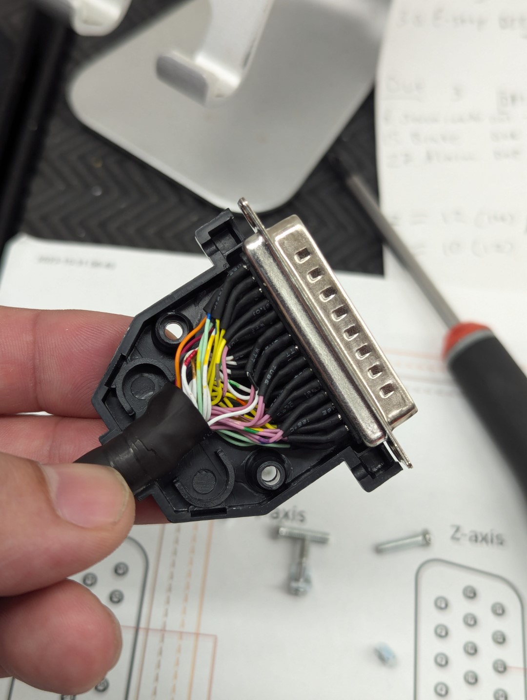
I cut it down a bit including the shielding before installing it in the cabinet and cutting the individual cables to length.


Last time I soldered the cables myself for the DB-44 connectors on the Delta B3 servo drives. This was very tedious as the DB-44 connectors are very densely packed and a small mistake where two cables had their insulation melt slightly during soldering caused a short circuit on humid day which partially fried one of the stepper outputs on the 7i96S board.
To avoid similar problems this time I bought a DB-44 cable from AliExpress for 39$ including shipping. It took a while to get the cable but when it finally arrived it looked okay and seems fairly well made.
I cut it down a bit including the shielding before installing it in the cabinet and cutting the individual cables to length.
Attachments:
The following user(s) said Thank You: besriworld
Please Log in or Create an account to join the conversation.
- Unlogic
- Offline
- Elite Member
-
Less
More
- Posts: 240
- Thank you received: 120
10 Sep 2024 11:30 - 10 Sep 2024 11:33 #309831
by Unlogic
Replied by Unlogic on topic Optimum Optimill MH50V CNC conversion
This is how the cabinet looks now with the 4th servo driver installed.

As always when modifying the cabinet with expensive electrical components the first power on was a bit scary. However there was no magic smoke but instead I was greeted with the most horrible fan noise I've ever come across.
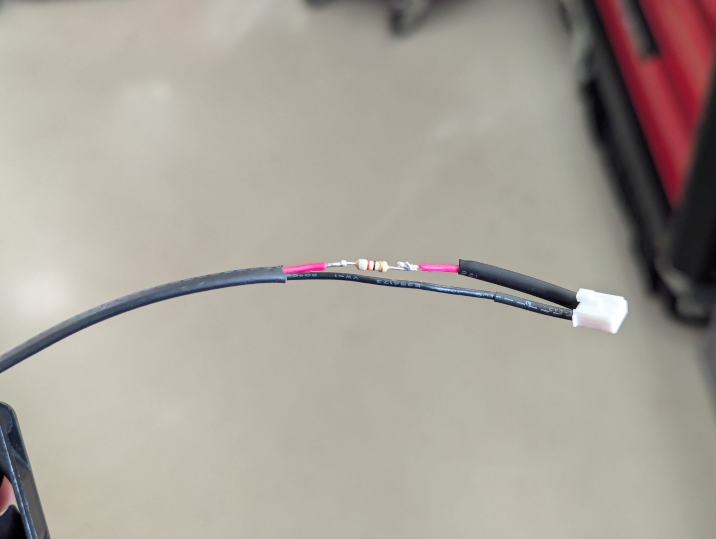
I promptly removed the new servo driver and popped off the side cover to find two small 40x40x15mm 24v fans rated at no less than 11 000 rpm!

I made a short term fix for now and soldered in a 80ohm 3w resistor for each fan to bring them down to 15v.

However they are is still far from quiet so I'll be monitoring the temperature of the spindle servo drive and see if I can get away with installing quieter fans.
Before I turned my attention to the configuration and HAL changes required for the new servo driver to work I replaced the keyboard attached to my control panel.
I had previously been using a full size keyboard but some functions in Probe Basic like selection of multiple lines in the editor (normally done with shift + arrow up/down) doesn't work without a mouse so I opted for a new old stock Microsoft All-on-One Media keyboard instead.

This keyboard is slightly vintage in IT terms but it has some features which I liked such as a dedicated left mouse button on the left side of the keyboard and touchpad which actually moves down when you click on in. This simplifies the use of the touchpad with gloves on.
To make sure that the keyboard stays in place while in use while at the same time be simple to remove when necessary I attached it with magnetic tape this time.


As always when modifying the cabinet with expensive electrical components the first power on was a bit scary. However there was no magic smoke but instead I was greeted with the most horrible fan noise I've ever come across.
I promptly removed the new servo driver and popped off the side cover to find two small 40x40x15mm 24v fans rated at no less than 11 000 rpm!
I made a short term fix for now and soldered in a 80ohm 3w resistor for each fan to bring them down to 15v.
However they are is still far from quiet so I'll be monitoring the temperature of the spindle servo drive and see if I can get away with installing quieter fans.
Before I turned my attention to the configuration and HAL changes required for the new servo driver to work I replaced the keyboard attached to my control panel.
I had previously been using a full size keyboard but some functions in Probe Basic like selection of multiple lines in the editor (normally done with shift + arrow up/down) doesn't work without a mouse so I opted for a new old stock Microsoft All-on-One Media keyboard instead.
This keyboard is slightly vintage in IT terms but it has some features which I liked such as a dedicated left mouse button on the left side of the keyboard and touchpad which actually moves down when you click on in. This simplifies the use of the touchpad with gloves on.
To make sure that the keyboard stays in place while in use while at the same time be simple to remove when necessary I attached it with magnetic tape this time.
Attachments:
Last edit: 10 Sep 2024 11:33 by Unlogic.
The following user(s) said Thank You: tommylight, besriworld
Please Log in or Create an account to join the conversation.
- besriworld
- Offline
- Elite Member
-
Less
More
- Posts: 315
- Thank you received: 84
10 Sep 2024 11:35 #309832
by besriworld
Replied by besriworld on topic Optimum Optimill MH50V CNC conversion
Good job!
The following user(s) said Thank You: Unlogic
Please Log in or Create an account to join the conversation.
- Unlogic
- Offline
- Elite Member
-
Less
More
- Posts: 240
- Thank you received: 120
10 Sep 2024 14:13 #309845
by Unlogic
Replied by Unlogic on topic Optimum Optimill MH50V CNC conversion
The configuration and HAL changes ended up taking over a day to figure out but in the end I managed to get spindle soft ramp up and ramp down in place along with encoder based RPM and actual spindle load displayed in Probe Basic.
I've attached my config files for Probe Basic in this post (note that the custom_tool_change.ngc file has to go in the subroutines folder). In this post I'll highlight the areas which were hardest to figure out. Hopefully Google picks them up this post so that other people searching for the same things find this post.

Here is current wiring schematics for reference:

I started with modifying my AXIS configuration using Pncconf. It has been virtually fool proof for generating configuration changes before but the values it generated when selecting a servo spindle in step/dir mode were for some reason not really spot on and it took me a while to figure what was going on as I was getting error about MAXVEL being too high right out of the box.
Currently I'm using the following values in the INI file for the spindle and the encoder:
The new spindle servo has a maximum RPM of 6000 rpm but I've set the limit at 4500 until I have replaced the spindle bearings.
The acceleration values are set very low to ensure a smooth ramp up/down as the servo motor has a lot of torque and makes a very violent starts otherwise.
I carefully matched the polarity for the differential encoder signals from the servo drive to the Mesa 7i96S board but for some reason I still hade to invert the encoder scale otherwise it was reading rotation in the wrong direction. It should also be noted that if you have for example a 1000 pulses per revolution (ppr) quadrature encoder the ENCODER_SCALE value set in the INI file needs to multiplied by four.
The 2kw Delta B3 servo drive for the spindle servo came with a default setting of 2500 ppr setting but I reconfigured it to 1250 ppr instead as 10 000 pulses per revolution felt a bit overkill.
I left the PID settings completely stock but as I'm using a close loop servo I'm not sure that PID should even be enabled as the drive handles that and even triggers a fault if there is too much deviation between the commanded position and the actual position.
When it came to the HAL file I had previously picked up on the fact that the stepgen on the Mesa board used to control the spindle should be enabled by machine-is-on and not spindle-enable as otherwise it would cause very abrupt stops of the spindle when using a servo.
Pncconf correctly generated the following line in my case:
However I was still getting very abrupt spindle stops which I tracked down to the following line in the HAL file:
That line controls the enable signal sent to the servo drive, without it the servo drive immediately stops.
I wanted the servo drive to ramp down slowly when stopped and then disable the drive so that I can rotate the spindle by hand when changing tools etc. I the end I solved this by using the great example posted by pippin88 in this thread (forum.linuxcnc.org/10-advanced-configura...ep-dir-servo-spindle).
With these values set the spindle enable signal remains active for an additional 3 seconds when the spindle stop signal is given which allows the spindle to ramp down softly according to the values set in the INI file.
When I had the spindle working properly with both ramp up and down I turned my attention to the user interface of Probe Basic.
In order to get the actual spindle RPM from the encoder to work the following line had to be added to the post gui file, in my case the custom.hal.
Getting the spindle load bar to work took only the following 3 lines.
The really magic part in those lines is the scalemax parameter which I would never have guessed existed or figured out how it worked if it wasn't for a few excellent posts from PCW on this forum.
As far as I have understood it the analog inputs on the 7i84 board by default scale from 0 to 36.3v. By changing the scale to go from 0 to 453.75 the max 8 volts which the servo drive analog output gives is translated to 100. This makes the spindle load bar in Probe Basic go from 0% to 100% as the voltage to the analog input varies from 0 to 8 volts.
I know that it would probably be better to have the spindle load bar in Probe Basic go from 0% to something like 150% or 200% to allow for higher peak loads to be displayed but I put that on the todo list for another day")
I've attached my config files for Probe Basic in this post (note that the custom_tool_change.ngc file has to go in the subroutines folder). In this post I'll highlight the areas which were hardest to figure out. Hopefully Google picks them up this post so that other people searching for the same things find this post.
Here is current wiring schematics for reference:
I started with modifying my AXIS configuration using Pncconf. It has been virtually fool proof for generating configuration changes before but the values it generated when selecting a servo spindle in step/dir mode were for some reason not really spot on and it took me a while to figure what was going on as I was getting error about MAXVEL being too high right out of the box.
Currently I'm using the following values in the INI file for the spindle and the encoder:
[SPINDLE_0]
MAX_VELOCITY = 4500
MAX_REVERSE_VELOCITY = 4500
MAX_ACCELERATION = 15
STEPGEN_MAXVEL = 93.75
STEPGEN_MAXACCEL = 30
P = 0.0
I = 0.0
D = 0.0
FF0 = 1.0
FF1 = 0.0
FF2 = 0.0
BIAS = 0.0
DEADBAND = 0.0
MAX_OUTPUT = 4500.0
ENCODER_SCALE = -5000
DIRSETUP   = 800
DIRHOLD    = 800
STEPLEN    = 1000
STEPSPACE  = 1000
STEP_SCALE = 5000
The new spindle servo has a maximum RPM of 6000 rpm but I've set the limit at 4500 until I have replaced the spindle bearings.
The acceleration values are set very low to ensure a smooth ramp up/down as the servo motor has a lot of torque and makes a very violent starts otherwise.
I carefully matched the polarity for the differential encoder signals from the servo drive to the Mesa 7i96S board but for some reason I still hade to invert the encoder scale otherwise it was reading rotation in the wrong direction. It should also be noted that if you have for example a 1000 pulses per revolution (ppr) quadrature encoder the ENCODER_SCALE value set in the INI file needs to multiplied by four.
The 2kw Delta B3 servo drive for the spindle servo came with a default setting of 2500 ppr setting but I reconfigured it to 1250 ppr instead as 10 000 pulses per revolution felt a bit overkill.
I left the PID settings completely stock but as I'm using a close loop servo I'm not sure that PID should even be enabled as the drive handles that and even triggers a fault if there is too much deviation between the commanded position and the actual position.
When it came to the HAL file I had previously picked up on the fact that the stepgen on the Mesa board used to control the spindle should be enabled by machine-is-on and not spindle-enable as otherwise it would cause very abrupt stops of the spindle when using a servo.
Pncconf correctly generated the following line in my case:
net machine-is-on => hm2_7i96s.0.stepgen.03.enableHowever I was still getting very abrupt spindle stops which I tracked down to the following line in the HAL file:
# --- SPINDLE-ENABLE ---
net spindle-enable  =>     hm2_7i96s.0.7i84.0.0.output-01
That line controls the enable signal sent to the servo drive, without it the servo drive immediately stops.
I wanted the servo drive to ramp down slowly when stopped and then disable the drive so that I can rotate the spindle by hand when changing tools etc. I the end I solved this by using the great example posted by pippin88 in this thread (forum.linuxcnc.org/10-advanced-configura...ep-dir-servo-spindle).
# --- timedelay before disable spindle output for deceleration ramp --- #
loadrt timedelay names=timedelay.spindle-enable-soft-stop
addf timedelay.spindle-enable-soft-stop servo-thread

setp timedelay.spindle-enable-soft-stop.on-delay 0
setp timedelay.spindle-enable-soft-stop.off-delay 3

net spindle-enable              =>     timedelay.spindle-enable-soft-stop.in
net spindle-enable-soft-stop    <=     timedelay.spindle-enable-soft-stop.out
net spindle-enable-soft-stop    =>     hm2_7i96s.0.7i84.0.0.output-01
With these values set the spindle enable signal remains active for an additional 3 seconds when the spindle stop signal is given which allows the spindle to ramp down softly according to the values set in the INI file.
When I had the spindle working properly with both ramp up and down I turned my attention to the user interface of Probe Basic.
In order to get the actual spindle RPM from the encoder to work the following line had to be added to the post gui file, in my case the custom.hal.
#Spindle RPM from encoder
net spindle-vel-fb-rpm => qtpyvcp.spindle-encoder-rpm.in
Getting the spindle load bar to work took only the following 3 lines.
#Spindle load (torque)
setp hm2_7i96s.0.7i84.0.0.analogin0-scalemax 453.75
net spindle-load <= hm2_7i96s.0.7i84.0.0.analogin0
net spindle-load => qtpyvcp.spindle-load-indicator.in-f
The really magic part in those lines is the scalemax parameter which I would never have guessed existed or figured out how it worked if it wasn't for a few excellent posts from PCW on this forum.
As far as I have understood it the analog inputs on the 7i84 board by default scale from 0 to 36.3v. By changing the scale to go from 0 to 453.75 the max 8 volts which the servo drive analog output gives is translated to 100. This makes the spindle load bar in Probe Basic go from 0% to 100% as the voltage to the analog input varies from 0 to 8 volts.
I know that it would probably be better to have the spindle load bar in Probe Basic go from 0% to something like 150% or 200% to allow for higher peak loads to be displayed but I put that on the todo list for another day
The following user(s) said Thank You: besriworld
Please Log in or Create an account to join the conversation.
- Unlogic
- Offline
- Elite Member
-
Less
More
- Posts: 240
- Thank you received: 120
10 Sep 2024 14:22 #309846
by Unlogic
Feels like I have been working on this thing forever. It felt a bit cumbersome to start tearing stuff apart again however the noise from the straight cut gears in the gearbox combined with low sustainable max spindle RPM really made this is a necessity as making parts with a spindle that only did 1500 rpm was way too slow (anything above 1500 made the gearbox sound like it was going into orbit).
I've looked at several completely new BT40 spindles on AliExpress but the listings often have very little technical information about the spindles and the sellers so far haven't been able to answer many of my questions so for now the spindle that came with the machine will have to do.
Replied by Unlogic on topic Optimum Optimill MH50V CNC conversion
Thank you!Good job!
Feels like I have been working on this thing forever. It felt a bit cumbersome to start tearing stuff apart again however the noise from the straight cut gears in the gearbox combined with low sustainable max spindle RPM really made this is a necessity as making parts with a spindle that only did 1500 rpm was way too slow (anything above 1500 made the gearbox sound like it was going into orbit).
I've looked at several completely new BT40 spindles on AliExpress but the listings often have very little technical information about the spindles and the sellers so far haven't been able to answer many of my questions so for now the spindle that came with the machine will have to do.
The following user(s) said Thank You: besriworld
Please Log in or Create an account to join the conversation.
- Unlogic
- Offline
- Elite Member
-
Less
More
- Posts: 240
- Thank you received: 120
16 Sep 2024 18:47 #310278
by Unlogic
Replied by Unlogic on topic Optimum Optimill MH50V CNC conversion
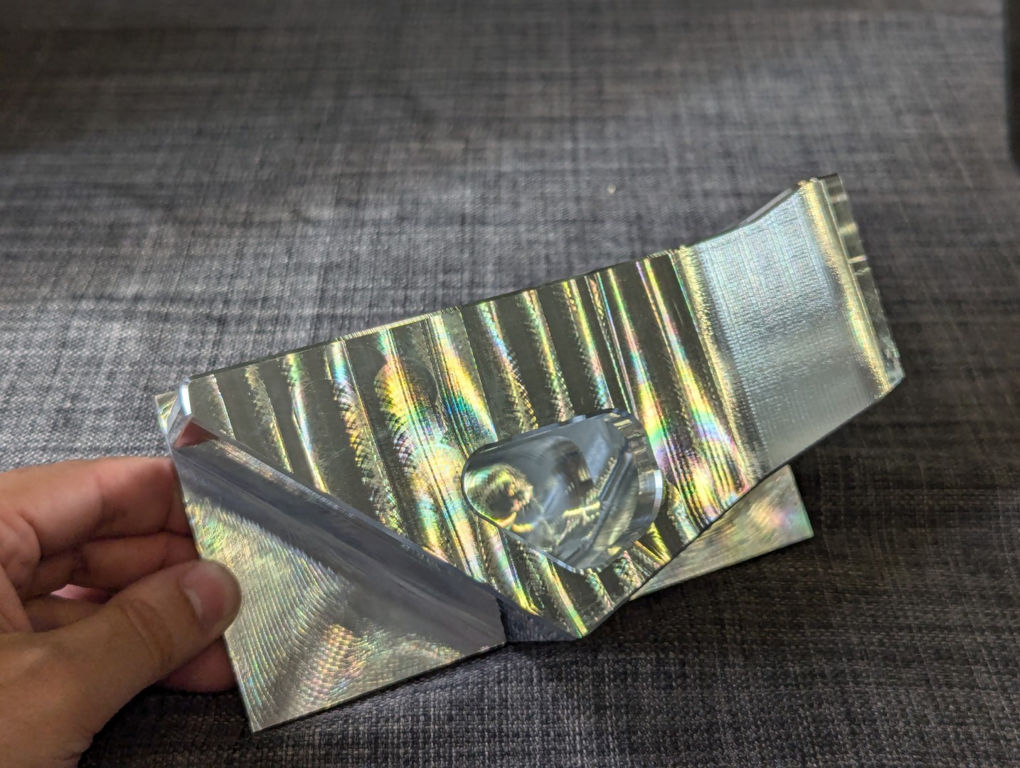
In order to test the new spindle motor I decided to mill a new polycarbonate shelf for my parallel blocks.
I milled the polycarbonate at 2500 rpm with very little noise however another issue crept up which I had overlooked, heat!
The old induction motor had a big fan on the back which not only cooled the motor but also indirectly cooled the head of the machine. Without any airflow the new spindle servo got pretty hot after running for an hour straight. The head of the machine was also uncomfortably hot.
In order to be able to finish milling the polycarbonate I ghetto rigged a small USB powered fan on top of the machine which did the trick.

Here is how the polycarbonate shelf came out.


I milled the polycarbonate at 2500 rpm with very little noise however another issue crept up which I had overlooked, heat!
The old induction motor had a big fan on the back which not only cooled the motor but also indirectly cooled the head of the machine. Without any airflow the new spindle servo got pretty hot after running for an hour straight. The head of the machine was also uncomfortably hot.
In order to be able to finish milling the polycarbonate I ghetto rigged a small USB powered fan on top of the machine which did the trick.
Here is how the polycarbonate shelf came out.
Attachments:
The following user(s) said Thank You: pommen
Please Log in or Create an account to join the conversation.
- Unlogic
- Offline
- Elite Member
-
Less
More
- Posts: 240
- Thank you received: 120
16 Sep 2024 18:51 #310279
by Unlogic
Replied by Unlogic on topic Optimum Optimill MH50V CNC conversion
In order to tackle the cooling of the servo motor and head of the machine I ordered two 80mm Ncotua branded fans.

I installed the fans in the top cover so they blow across the head of the machine including the toothed belt and then onto the spindle servo motor.


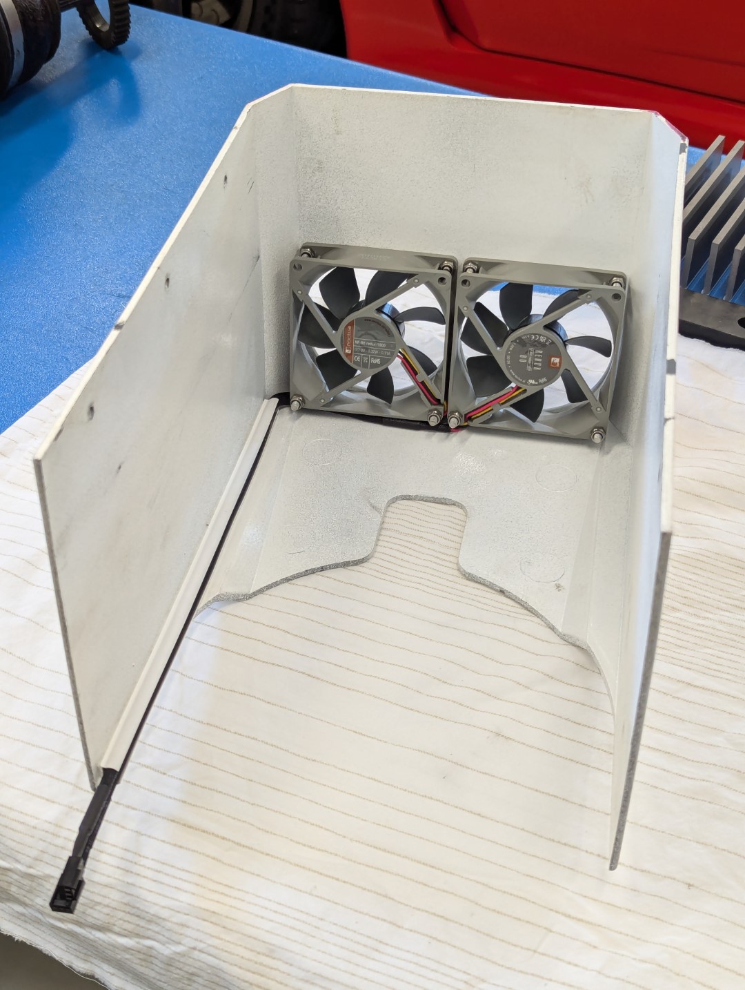

I wired the two 12v fans in series and power them with 24v from one of the outputs of the Mesa 7i84 expansion card in the control cabinet.
In order to have the operation of the fans automatically controlled I added a line of HAL code to my LinuxCNC configuration which slaves them to the spindle-enable signal.
Next up is the replacement of the spindle bearings which have been making bad noises for quite some time...
I installed the fans in the top cover so they blow across the head of the machine including the toothed belt and then onto the spindle servo motor.
I wired the two 12v fans in series and power them with 24v from one of the outputs of the Mesa 7i84 expansion card in the control cabinet.
In order to have the operation of the fans automatically controlled I added a line of HAL code to my LinuxCNC configuration which slaves them to the spindle-enable signal.
Next up is the replacement of the spindle bearings which have been making bad noises for quite some time...
Attachments:
The following user(s) said Thank You: tommylight, pommen, besriworld
Please Log in or Create an account to join the conversation.
- Unlogic
- Offline
- Elite Member
-
Less
More
- Posts: 240
- Thank you received: 120
20 Sep 2024 16:01 #310522
by Unlogic
Replied by Unlogic on topic Optimum Optimill MH50V CNC conversion
I did the first proper test of the new spindle servo motor today milling some 7050 aluminium.
The test was done using a 80 mm face mill at 100% width of cut, 0,5 mm depth of cut, 2000 rpm and a feedrate of 600 mm/minute. This worked splendid.
Not only is the machine much quieter but the finish at high feed rates is noticable improved which was unexpected. I suspect that this is the result of removing all the gears and shafts from the transmission as there are much less vibrations from the head now.
The following user(s) said Thank You: tommylight
Please Log in or Create an account to join the conversation.
- Unlogic
- Offline
- Elite Member
-
Less
More
- Posts: 240
- Thank you received: 120
04 Oct 2024 12:32 #311278
by Unlogic
Replied by Unlogic on topic Optimum Optimill MH50V CNC conversion
The servo belt drive for the spindle has proven to be a great upgrade. Milling 7050 aluminum with this 20 mm roughing end mill is like cutting butter.
However my already noisy spindle bearings didn't like the extra torque and rpm for very long so after partially machining the part below I had to pause and replace the bearings...


While I had the machine apart I decided to install a pneumatic tool release cylinder.


In order to safely trigger the tool release I used the toggle, and, not components to create a HAL logic which only enabled to tool release button if the spindle is not enabled. And while the tool release is in progress it inhibits machine and spindle motion.
The HAL code for this was pretty straight forward.
However I banged my head against component conflicts for quite some time. First I tried the HAL TWOPASS setting which to my great surprise didn't work. Upon reading the documentation a bit more closely I realized that the TWOPASS option doesn't work for postgui HAL files which is exactly what I was dealing with here.
The conflict ended up being caused by the stock probe_basic_postgui.hal file which loads some components before chain loading my custom.hal file. My custom.hal in turn chain loads a separate run_pause.hal file (the excellent run/step/resume code from BigJohnT). I had to consolidate all these files as it made not sense to have the code spread out if they ended up being dependent on each other any way.
After sorting that out the tool release logic works great. Thought this could be useful information for other rookies who come across this problem.
However my already noisy spindle bearings didn't like the extra torque and rpm for very long so after partially machining the part below I had to pause and replace the bearings...
While I had the machine apart I decided to install a pneumatic tool release cylinder.
In order to safely trigger the tool release I used the toggle, and, not components to create a HAL logic which only enabled to tool release button if the spindle is not enabled. And while the tool release is in progress it inhibits machine and spindle motion.
The HAL code for this was pretty straight forward.
#Pneumatic tool release
loadrt toggle names=tool-change-toggle
loadrt and2 names=and-tool-change
loadrt not names=spindle-not-enabled

addf tool-change-toggle servo-thread
setp tool-change-toggle.debounce 5
addf spindle-not-enabled servo-thread
addf and-tool-change servo-thread

net tool-change-button <= hm2_7i96s.0.7i84.0.0.input-14
net spindle-enable-soft-stop => spindle-not-enabled.in
net spindle-disabled <= spindle-not-enabled.out

net tool-change-button => and-tool-change.in0
net spindle-disabled => and-tool-change.in1

net trigger-tool-change <= and-tool-change.out
net trigger-tool-change => tool-change-toggle.in

net tool-change-toggled <= tool-change-toggle.out
net tool-change-toggled => hm2_7i96s.0.7i84.0.0.output-04
net tool-change-toggled => spindle.0.inhibit
net tool-change-toggled => motion.feed-inhibit
However I banged my head against component conflicts for quite some time. First I tried the HAL TWOPASS setting which to my great surprise didn't work. Upon reading the documentation a bit more closely I realized that the TWOPASS option doesn't work for postgui HAL files which is exactly what I was dealing with here.
The conflict ended up being caused by the stock probe_basic_postgui.hal file which loads some components before chain loading my custom.hal file. My custom.hal in turn chain loads a separate run_pause.hal file (the excellent run/step/resume code from BigJohnT). I had to consolidate all these files as it made not sense to have the code spread out if they ended up being dependent on each other any way.
After sorting that out the tool release logic works great. Thought this could be useful information for other rookies who come across this problem.
Attachments:
The following user(s) said Thank You: tommylight, COFHAL, 7strideR
Please Log in or Create an account to join the conversation.
Moderators: piasdom
Time to create page: 1.491 seconds