
- Posts: 62
- Thank you received: 30
ColorCNC Colorlight 5A-75E/5A-75B as FPGA controller board
- muvideo
- Offline
- Senior Member
-

Less
More
4 years 5 months ago - 4 years 5 months ago #244149
by muvideo
Replied by muvideo on topic ColorCNC Colorlight 5A-75E/5A-75B as FPGA controller board
Wow, thanks for updating the naming convention for gpio and pwm.
Small testing update:
the bug on last output pin is solved, unfortunately I'm still not being successful at reading inputs. Verified the hardware with my own fw and the pins are being read ok.
Also I'm not able to get the stepgen to work.
Dont know if there is something wrong in my hal file, I uploaded it for your reference
a few messages back.
Small "problem" on pwm: if frequency is set to zero the pin will spit out a 25MHz square wave at 50% duty.
Thanks!
Fabio
Last edit: 4 years 5 months ago by muvideo.
The following user(s) said Thank You: TOLP2
Please Log in or Create an account to join the conversation.
- svb
- Offline
- Senior Member
-
Less
More
- Posts: 44
- Thank you received: 10
4 years 5 months ago #244150
by svb
Replied by svb on topic ColorCNC Colorlight 5A-75E/5A-75B as FPGA controller board
Big thanks, compiled ok and Litex part, and bitstream. On next week receive 75b & 75e boards and start tests
Please Log in or Create an account to join the conversation.
- TOLP2
- Offline
- Elite Member
-

Less
More
- Posts: 225
- Thank you received: 178
4 years 5 months ago #244151
by TOLP2
Replied by TOLP2 on topic ColorCNC Colorlight 5A-75E/5A-75B as FPGA controller board
Hey Fabio, thanks for testing.
At this moment I have reproduced your problem with stepgen and am planning to solve this coming week. Not sure yet whether it is a problem with communication or the card.
About PWM: when the frequency is set to 0 it switches over to PDM (pulse density modulation), therefore you see a frequency of 25 MHz. It should still obey the enable and value pin, what were your inputs on these?
For the Gpio in: would you be willing able to run a modified version of the driver which prints out the received bytes from the card? This way we can pinpoint the problem to the card or driver. I can make a special branch for this tomorrow.
Please Log in or Create an account to join the conversation.
- muvideo
- Offline
- Senior Member
-
Less
More
- Posts: 62
- Thank you received: 30
4 years 5 months ago - 4 years 5 months ago #244201
by muvideo
Replied by muvideo on topic ColorCNC Colorlight 5A-75E/5A-75B as FPGA controller board
Sure, no prob.
It would be useful to have a jtag bridge added to soc to peek at registers.
About PDM modulation, honestly didnt check the behavior changing the value, next time I'll do.
Edit about PDM:
I think has some initialization problem: the output is correct only after value becomes other than zero
in PDM mode (frequency zero). Otherwise the output will be 50% 25MHz whenever value is zero and frequency is zero.
After value becomes nonzero at least once in PDM mode, then the behavior is correct.
Last edit: 4 years 5 months ago by muvideo. Reason: PDM update
Please Log in or Create an account to join the conversation.
- TOLP2
- Offline
- Elite Member
-
Less
More
- Posts: 225
- Thank you received: 178
4 years 5 months ago - 4 years 5 months ago #244241
by TOLP2
Replied by TOLP2 on topic ColorCNC Colorlight 5A-75E/5A-75B as FPGA controller board
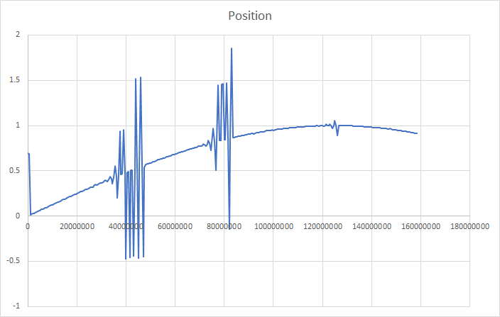
Today some fun with the problem with the stepgen. After flattening some bugs in the code, I was getting some stability problems with the position, which happened periodically. The problem arises from the stepgen module handing off all acceleration calculations to the FPGA, similar as the implementation of the software stepgen of LinuxCNC. When going to 50 MHz the acceleration per timestep gets infinitely small, as the time component is being squared. Result is that while the driver thinks acceleration is handled by the FPGA, the FPGA sees a max acceleration of 0 and hence applies the commanded speed directly. Why does the spikes occur periodically: basically it is a combination of chance (the thread period is not really a constant) and an ever increasing error. Note: this figure is already after optimisation of the algorithm.
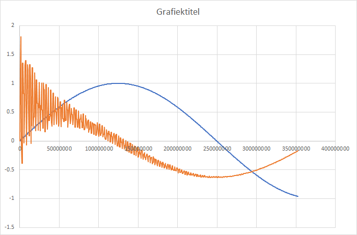
OK: what happens if we throw in some values which make sure that the max acceleration which is send to the FPGA is not equal to 0. So, we use a relatively high acceleration. Now we see we get a relatively smooth curve. We are not there yet, as the orange line depicts the speed of the stepper engine fluttering around. The most probably cause is now in the speed prediction.
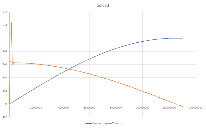
When flattening out the last bugs in the speed prediction it now looks reasonable. The reason for the spike at the start is that the position-cmd is directly coupled to the signal generator. So when starting, the commanded position does not adhere to any acceleration limits. The stepgen therefore has to catch up
The code is not yet on GitHub, because:
OK: what happens if we throw in some values which make sure that the max acceleration which is send to the FPGA is not equal to 0. So, we use a relatively high acceleration. Now we see we get a relatively smooth curve. We are not there yet, as the orange line depicts the speed of the stepper engine fluttering around. The most probably cause is now in the speed prediction.
When flattening out the last bugs in the speed prediction it now looks reasonable. The reason for the spike at the start is that the position-cmd is directly coupled to the signal generator. So when starting, the commanded position does not adhere to any acceleration limits. The stepgen therefore has to catch up
The code is not yet on GitHub, because:
- needs some good cleaning up (too tired for today);
- it only works with large values of accelerations (20,000 steps/second²), this needs also to be addressed.
Last edit: 4 years 5 months ago by TOLP2. Reason: Found solution
The following user(s) said Thank You: tommylight, muvideo, svb
Please Log in or Create an account to join the conversation.
- TOLP2
- Offline
- Elite Member
-
Less
More
- Posts: 225
- Thank you received: 178
4 years 4 months ago #244470
by TOLP2
Replied by TOLP2 on topic ColorCNC Colorlight 5A-75E/5A-75B as FPGA controller board
Today I pushed 5 commits for various reasons:
- the 50% duty-cycle for PDM on start up has been resolved;
- several errors in the Stepgen firmware have been resolved. The firmware now does exactly what the computer commands it to do; no question about it. Took some time to debug the reset mechanism. In Python it is easy to say if not ... , In Verilog ~... doesn't do the same. It is a bit-wise operator, so when one of the bits is zero, it still returns True. That was unexpected ... stems from mixing two languages together (Python / Verilog).
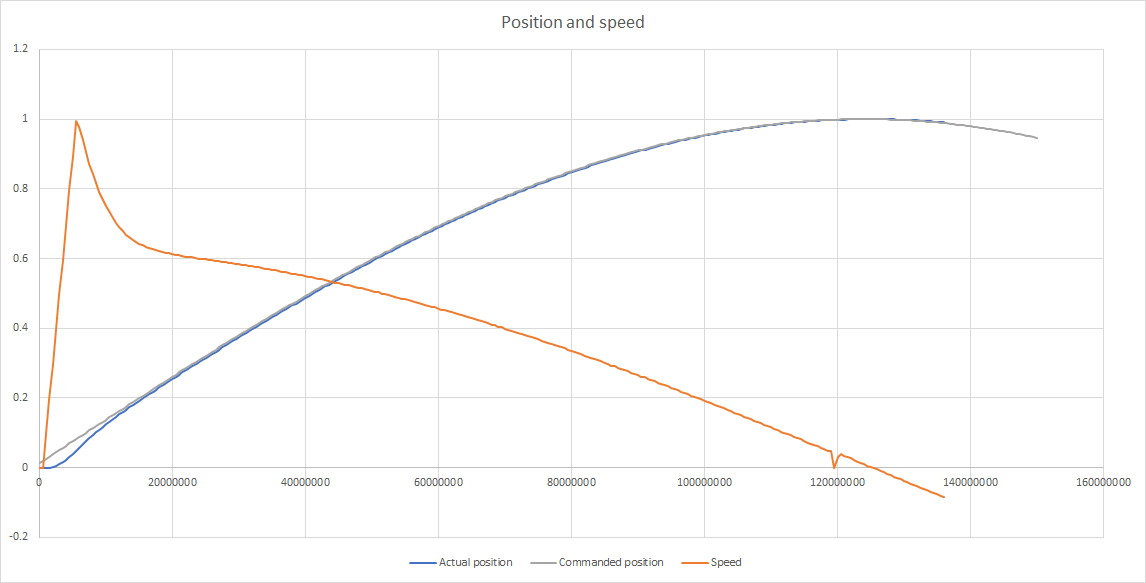
- the driver for the stepgen has been overhauled to resolve the instabilities of the stepper. As long as the acceleration limits are respected, the driver follows very well. As soon as there is a following error, it takes longer then my liking to reduce this error. At this moment I'm more focused on unconditional stability (thus damping) then reducing the error as quick as possible for the case where acceleration limits are not taken into aacount.
- added a flag for showing debug output of the stepgen (<card-name>.stepgen.##.debug). This shows the state of the hal-pins commanded position, position received, position estimate at the start of next cycle, speed received, speed estimate at the start of next cycle, required average speed for next cycle, match time (time required to get to that speed) and new commanded speed (including method how it is arrived.
- added a flag for debugging the data-stream between the machine and the FPGA (<card-name>.debug). @muvideo: can you set this flag to True and see whether the FPGA sends the data to the PC when you apply your GPIO in and post the results here? Easiest way is to first start the HAL, set the input of the GPIO and then set the pin to True. Note, this will generate a lot of output on your screen, only one cycle will suffice to post here.
The following user(s) said Thank You: tommylight, muvideo, svb
Please Log in or Create an account to join the conversation.
Moderators: PCW, jmelson
Time to create page: 1.098 seconds