Light Machine Corp. Benchman XTr (retrofit)
- x-Intelitek Engineer
- Offline
- Premium Member
-

Less
More
- Posts: 113
- Thank you received: 22
18 Jan 2017 17:38 #86071
by x-Intelitek Engineer
Replied by x-Intelitek Engineer on topic Light Machine Corp. Benchman XTr (retrofit)
Rex,
Also, depending on the vintage of your machine, we may be able to move some jumpers on the control board to ignore the 4th axis not being being plugged in. But if you have a flood coolant machine, you really want that connector on the rear wall sealed.
Don
Also, depending on the vintage of your machine, we may be able to move some jumpers on the control board to ignore the 4th axis not being being plugged in. But if you have a flood coolant machine, you really want that connector on the rear wall sealed.
Don
Please Log in or Create an account to join the conversation.
- dynamyte24
-
- Offline
- New Member
-

Less
More
- Posts: 15
- Thank you received: 1
18 Jan 2017 17:56 - 18 Jan 2017 18:13 #86072
by dynamyte24
Replied by dynamyte24 on topic Light Machine Corp. Benchman XTr (retrofit)
Don,
Thanx for the info on the 4th axis jumper plug.
I just got off the phone with Trevor at Intelitek and have a jumper on the way!
I'd like to have the info about jumpering on the board itself, as I'm not certain
that the 4th axis connector on the back wall is the OEM unit.
Yes, my machine has flood coolant.
I have no qualms as to using my DVM and jumper leads.
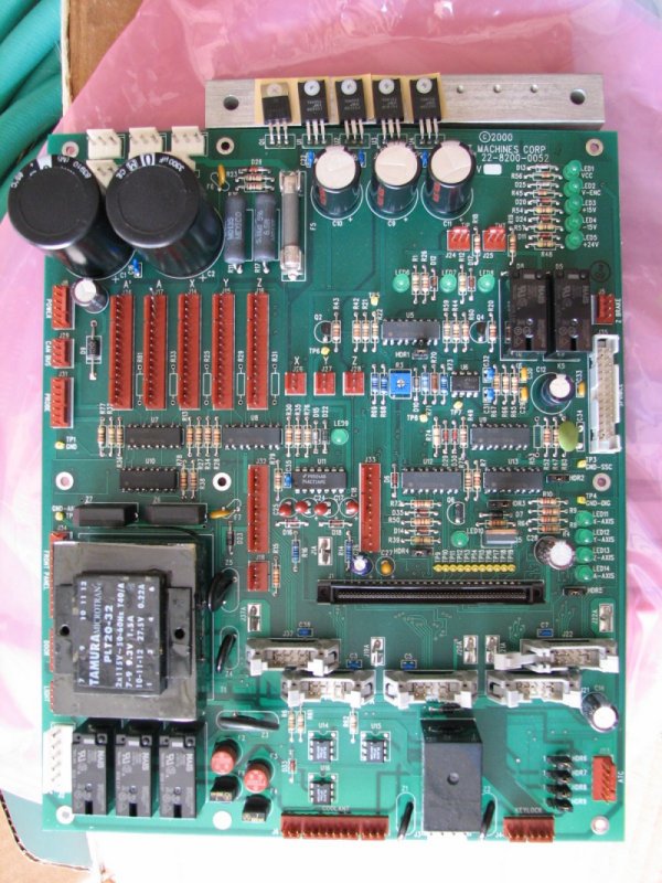
I've attached a pic of my spare main board, which as far as I can tell is identical to the board in the machine.
Rex
Thanx for the info on the 4th axis jumper plug.
I just got off the phone with Trevor at Intelitek and have a jumper on the way!
I'd like to have the info about jumpering on the board itself, as I'm not certain
that the 4th axis connector on the back wall is the OEM unit.
Yes, my machine has flood coolant.
I have no qualms as to using my DVM and jumper leads.
I've attached a pic of my spare main board, which as far as I can tell is identical to the board in the machine.
Rex
Last edit: 18 Jan 2017 18:13 by dynamyte24.
Please Log in or Create an account to join the conversation.
- x-Intelitek Engineer
- Offline
- Premium Member
-
Less
More
- Posts: 113
- Thank you received: 22
18 Jan 2017 18:33 #86076
by x-Intelitek Engineer
Replied by x-Intelitek Engineer on topic Light Machine Corp. Benchman XTr (retrofit)
Rex,
My questions about the DVM and jumper leads was meant for TGTROPIC and his troubleshooting issues.
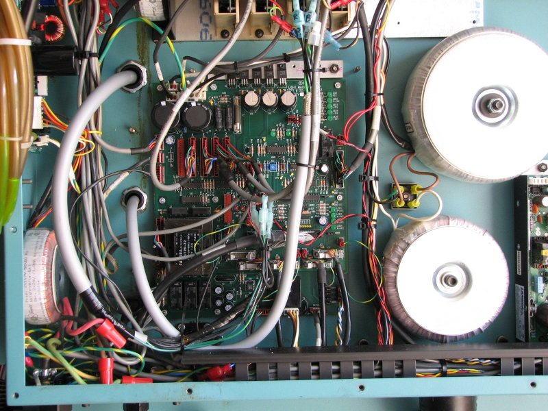
From your photos, you do have the OEM 4th axis connector. I can see the top of it in the wall just below K1, K2, & K3 on the control board.
To change the jumpers to make the machine a 3-axis machine, move HDR2 to the left two pins (1-2), for a 4-axis, move HDR2 to the right two pins (2-3).
Don
My questions about the DVM and jumper leads was meant for TGTROPIC and his troubleshooting issues.
From your photos, you do have the OEM 4th axis connector. I can see the top of it in the wall just below K1, K2, & K3 on the control board.
To change the jumpers to make the machine a 3-axis machine, move HDR2 to the left two pins (1-2), for a 4-axis, move HDR2 to the right two pins (2-3).
Don
The following user(s) said Thank You: dynamyte24, cncamateur
Please Log in or Create an account to join the conversation.
- x-Intelitek Engineer
- Offline
- Premium Member
-
Less
More
- Posts: 113
- Thank you received: 22
18 Jan 2017 21:03 #86092
by x-Intelitek Engineer
Replied by x-Intelitek Engineer on topic Light Machine Corp. Benchman XTr (retrofit)
To avoid hijacking this topic, TGTROPIC and I have taken our troubleshooting off forum.
Don
Don
The following user(s) said Thank You: MacGalempsy
Please Log in or Create an account to join the conversation.
- dynamyte24
-
- Offline
- New Member
-
Less
More
- Posts: 15
- Thank you received: 1
18 Jan 2017 23:08 #86102
by dynamyte24
Don,
Thanx so much for the 3-4axis jumper info. I just ran over to my shop to try it out, and it lit right off with no 4th axis encoder error.
Life is good!!
Rex
Replied by dynamyte24 on topic Light Machine Corp. Benchman XTr (retrofit)
To change the jumpers to make the machine a 3-axis machine, move HDR2 to the left two pins (1-2), for a 4-axis, move HDR2 to the right two pins (2-3).
Don,
Thanx so much for the 3-4axis jumper info. I just ran over to my shop to try it out, and it lit right off with no 4th axis encoder error.
Life is good!!
Rex
Please Log in or Create an account to join the conversation.
- x-Intelitek Engineer
- Offline
- Premium Member
-
Less
More
- Posts: 113
- Thank you received: 22
19 Jan 2017 13:23 #86144
by x-Intelitek Engineer
Replied by x-Intelitek Engineer on topic Light Machine Corp. Benchman XTr (retrofit)
Rex,
Just remember that if you run it this way with flood coolant and you get coolant into the unprotected 4th axis connector inside the machine, it is a HUGE PAIN IN THE NECK to clean it out.
Don
Just remember that if you run it this way with flood coolant and you get coolant into the unprotected 4th axis connector inside the machine, it is a HUGE PAIN IN THE NECK to clean it out.
Don
Please Log in or Create an account to join the conversation.
- MacGalempsy
- Offline
- Senior Member
-

Less
More
- Posts: 68
- Thank you received: 2
29 Jan 2017 15:15 #86907
by MacGalempsy
Replied by MacGalempsy on topic Light Machine Corp. Benchman XTr (retrofit)
Guys, I would like a little input on the 2 sensors, which I am assuming are hall effect detectors. I can get the one on the spindle to go true when rotating the spindle. My plan is to use this as feedback for my tool changing ladder program. The second one, I cannot seem to get to work, possibly its bad. I assume this one is for the power drawbar, but would like a better understanding of the system before tearing it apart. Is there a magnet? Does the spindle need to be oriented? Anyone got an assembly drawing available? Any help is much appreciated.
Please Log in or Create an account to join the conversation.
- Azik1
- Offline
- New Member
-
Less
More
- Posts: 8
- Thank you received: 2
29 Jan 2017 15:39 #86909
by Azik1
Replied by Azik1 on topic Light Machine Corp. Benchman XTr (retrofit)
Mac, if you send me photo of your draw bar assembly i might be able to help you with sensor.
Both sensors on my machine is inductive proximity sensors.
The one that senses drawbar open-close state is very finicky to tune properly, i think i nailed procedure thought that made it working reliably. You may need to remove air cylinder to gain full access to the sensor.
Attached is the drawing i got for my machine, but it does not show sensor.
The following user(s) said Thank You: MacGalempsy
Please Log in or Create an account to join the conversation.
- MacGalempsy
- Offline
- Senior Member
-
Less
More
- Posts: 68
- Thank you received: 2
29 Jan 2017 16:35 #86913
by MacGalempsy
Replied by MacGalempsy on topic Light Machine Corp. Benchman XTr (retrofit)
Thank you, that looks like the right diagram. What did you do to dial it in?
Please Log in or Create an account to join the conversation.
- Azik1
- Offline
- New Member
-
Less
More
- Posts: 8
- Thank you received: 2
29 Jan 2017 17:00 #86915
by Azik1
Replied by Azik1 on topic Light Machine Corp. Benchman XTr (retrofit)
Make sure you have means to read state of the sensor in real-time in your software (kflop makes it easy)
Install tool holder into the clamp.
Then remove air cylinder for draw bar (4 larger and long screws) it will give you access to the sensor wire and sensor itself (wire is clamped by small flat plate which is easy to remove)
Once air cylinder is removed then locate tiny set screw on the side of draw-bar assembly that is pressing to the body of the cylindrical pickup sensor (it is inside one of the holes on the side of the assembly), you need to loosen it and then you can move sensor wire by hand.
Pull or push sensor by holding wire just tiny bit until it indicates draw bar clamped state. Important to get it right on the edge of sensitivity, if it is pushed in too much washer will rub on it or it will not sense draw-bar open.
Very gently and lightly tighten set screw, sensor has very soft body and set screw can push into it easy.
Having tool holder installed will leave enough clearance for washer to get closer to the sensor in case you close draw-bar without tool holder in it. I found that if i calibrate without tool holder then sensor can be too close to the washer and will not reliably sense washer away state when draw-bar is opened.
The following user(s) said Thank You: MacGalempsy
Please Log in or Create an account to join the conversation.
Time to create page: 0.330 seconds