image missing http://i346.photobucket.com/albums/p431/swill008/2015-11/0F0204B0-54BA-424F-BC72-4491C437E997_zpsgo5hlmfs.jpg
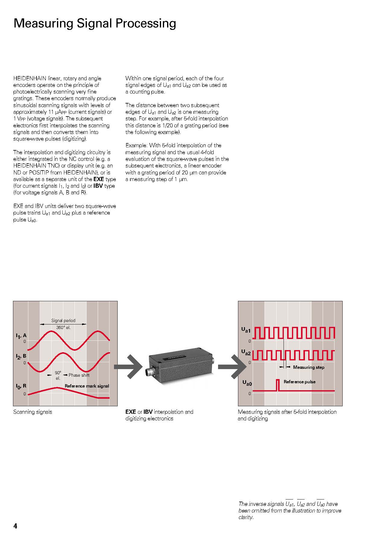
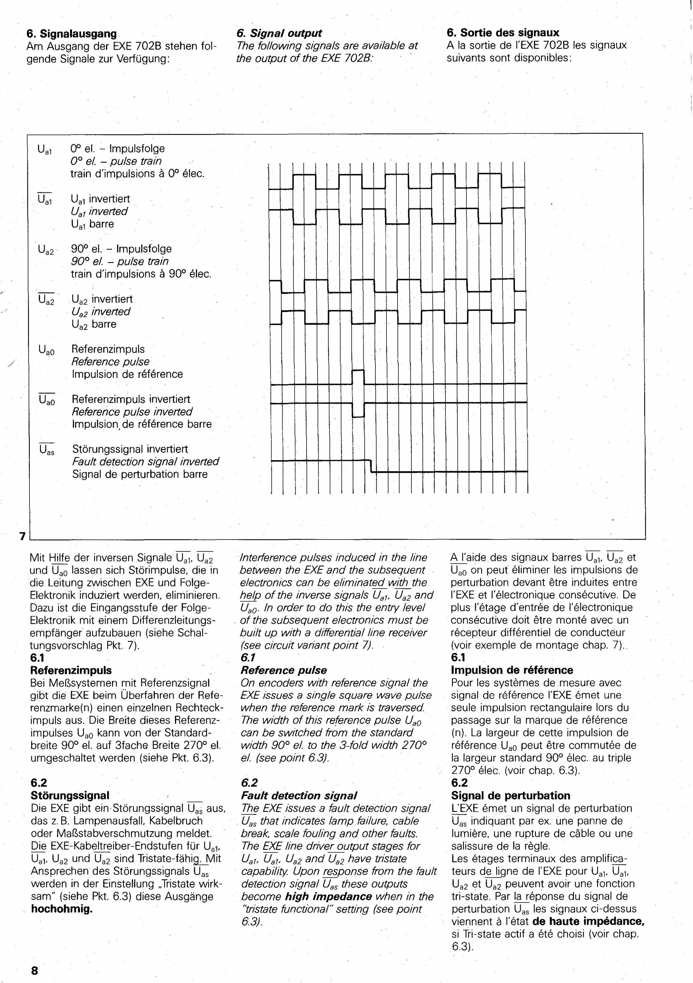
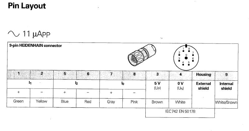
Ok I'm using cat5 cable for one 702B exe box. But ran into a snag.
The 7i77 pin outs don't match my EXE box. I have these as attached.
The 7i77 is listed with:
QA0
QB0
IDX
GND assuming same as 0volt
My box doesn't seem to need the 5Volt so I'll try omitting it.
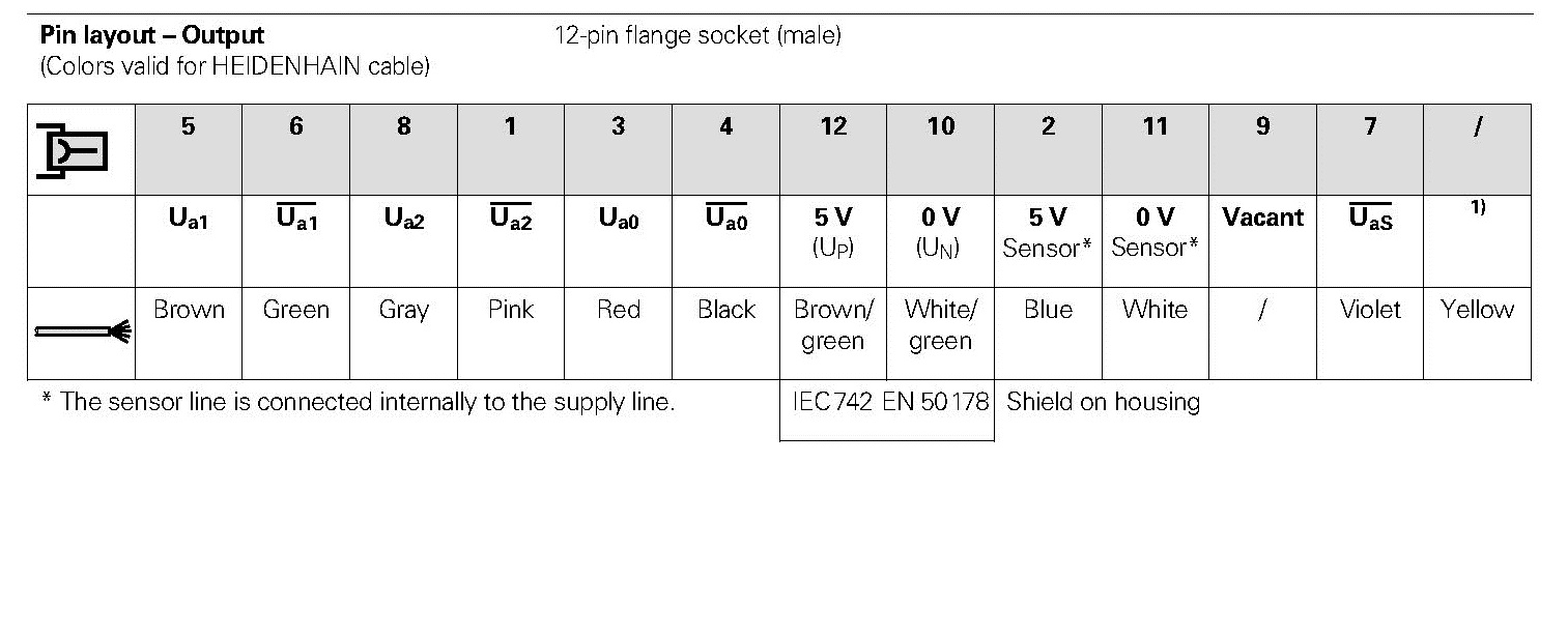
But my EXE is;
A0
A1
A2
As
0V
Anyone know where I can read to match up for certain where each go to the 7i77?
I'm not sure what each signal means besides the GND/0V.
Just guessing but I would assume:
A0 -A0
GND-0V
B0-A2
IDX-AS
??
EDIT:
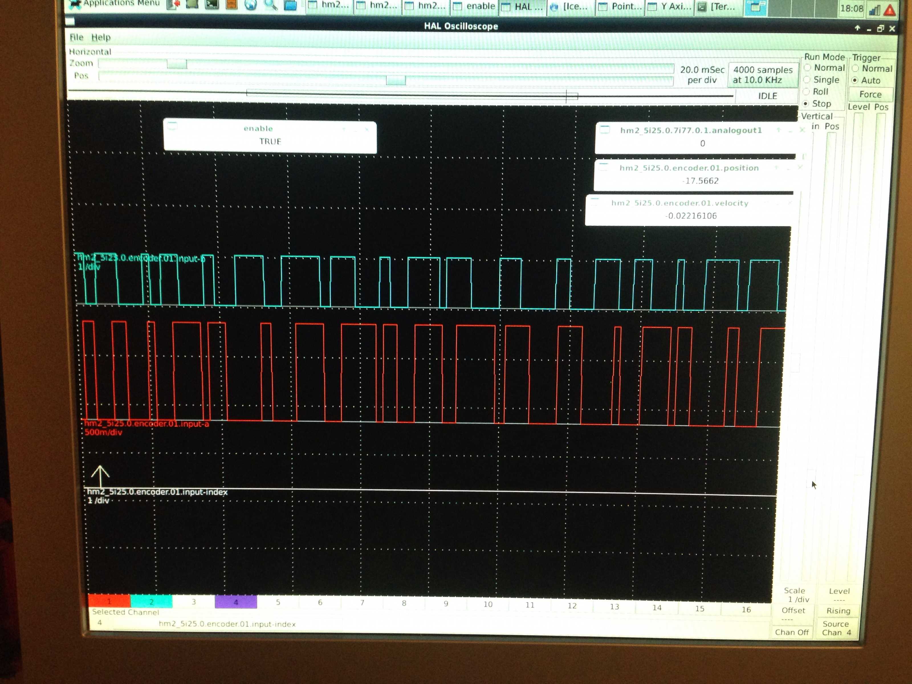
Ok, I can see A & B TTL signals, not sure from which pins, A1 = A phase and A2 = B phase. I believe because I'm not sure what the 7i77 Pin-out is expecting. On the 7i77 I have wired [a0 = QA0], [a1 = QB0] and [a2 = IDX].
I can not see an index pulse from the encoder, so I expect I have this setup wrong. I also have switched around the wiring numerous times, so now I'm not sure how I have it wired now that I'm at work! lol
I really need to know what the 7i77 encoder pin-outs are expecting. I'm thinking this:
Qa0= A phase TTL
Qb0= B phase TTL
IDX= Index pulse
Then I need to figure out what my signals are from my exe box. After work I plan on just connecting each set / one at a time and look at it from HAL scope and see what it produces. As wired at the moment, I can see the TTL signals, but my velocity and encoder position doesn't seem correct.
Position only moves one direction - even when I turn it by hand