Planning - Bridgeport Interact 1 linuxCNC Retrofit
- cncnoob1979
-
 Topic Author
- Offline
- Platinum Member
-

- Posts: 403
- Thank you received: 75
Thanks a TON for the files. Now I can peek at them!
Please Log in or Create an account to join the conversation.
- cncnoob1979
-
 Topic Author
- Offline
- Platinum Member
-

- Posts: 403
- Thank you received: 75
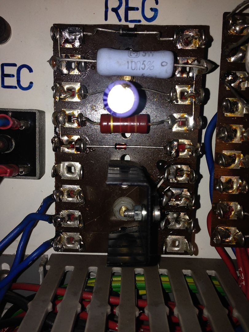
For my Mini ATX motherboard I ordered a PicoPSU 160W with 180Watt power brick. After finding out the max power draw of my motherboard I should be able to disconnect the PicoPSU power brick and plug direct 12v to it from the RD65A. From the reviews these little PicoPSU's are awesome. Ill tell you what I think after I get it all going.
I need to read about ground loops and how to wire all these different power supply together to prevent any issues. Can someone point me to a article they recommend? Most of what I have read has been in general terms and I'm trying to wrap my head around it.
Mean Well RD-65A Data Sheet
Web Site PicoPSU 160W
Please Log in or Create an account to join the conversation.
- TntSalad
-

- Offline
- New Member
-

- Posts: 10
- Thank you received: 0
www.google.com/url?sa=t&source=web&rct=j...L07Y02MKd15X1ufA9c2Q
But don't get too caught up in all this most of your logic is discrete, unless you have bigger issues its fairly immune to noise just make sure your analog signals and encoders are isolated and in in differential.
Oh yeah twisted pair shielded wires help!!!
Please Log in or Create an account to join the conversation.
- cncnoob1979
-
 Topic Author
- Offline
- Platinum Member
-

- Posts: 403
- Thank you received: 75


Tntsalad,
I will be using Ethernet CAT6 cabling with my signals from the exe boxes to my 7i77. I'll be using stock cabling from my encoders to the exe boxes.
So that should shield them. I'm mainly cautious over my different power supplies. I wonder if I should "float" them. Or just make sure they are grounded in the same location as the rest of my electronics.
Ok, so I ;
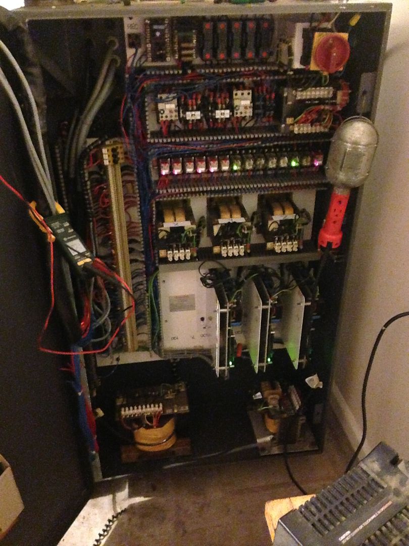
Repaired the 24v system and replaced all my relays.
I like them. Now I can see exactly which relay that is activated.
So, I'm back where I started. Just with a little bit more knowledge and a healthy attitude towards double checking my assumptions
Please Log in or Create an account to join the conversation.
- TntSalad
-

- Offline
- New Member
-

- Posts: 10
- Thank you received: 0
AC transformers should also be grounded in most cases if not, when you grab onto something(that should be safe otherwise, such as the case of transformer) in your machine, you will automatically float yourself up to that potential, and if you grab something else(cabinet for example) while doing that you will become a conductor, applies to DC here also. Hope this answers it, if not we can set up a chat on skype or similar one of this days.
Please Log in or Create an account to join the conversation.
- cncnoob1979
-
 Topic Author
- Offline
- Platinum Member
-

- Posts: 403
- Thank you received: 75
I don't believe I'm making myself clear. The entire machine is exactly the same as it was engineered. I haven't made any changes from the original configuration. I'm concerned with the additions I'll be making. Two power supplies at the moment. I think I will just isolate them in the Pendant housing and run the grounds to the original grounding plane, approximately 4 ft run to my grounding point .
I would never disconnect an AC grounding point --- OUCH. Other than my previous mistake I have a pretty decent understanding of electricity. Ive got the basics down! lol
Please Log in or Create an account to join the conversation.
- TntSalad
-

- Offline
- New Member
-

- Posts: 10
- Thank you received: 0
Please Log in or Create an account to join the conversation.
- cncnoob1979
-
 Topic Author
- Offline
- Platinum Member
-

- Posts: 403
- Thank you received: 75
I started wiring my inputs to the board. I have linuxcnc booting with a minimal configuration. I can jog each axis but of course receive a following error because I have not connected my encoders of yet. Just trying to get each thing done one at a time. I'm confused on the function of the enable signals on the 7i77. Its clear as mud in my mind as of now!
Question:
Can someone explain to me in layman terms how I could connect my Servo AMPS enable to the enable inputs on the 7i77?
My enables are connected to a 24v DC relay. I have [1] 24vdc connection to each relay that requires 24vdc to activate the relay to pass my enable signal to my amps.
[Output rating of the switches is 50 mA max at 100VDC max] reading this; can I connect my 24vdc relay input to the ENA0+ and connect my DC -(NEG) common to ENA-?
I'm being very cautious because they are polarity sensitive and I don't want to destroy my 7i77.
TB5 is the 7I77s analog drive interface connector. It has both the +-10V analog
outputs and the drive enable connections. Each drive interface uses 4 pins. TB5 is a 24
pin 3.5 MM pluggable terminal block supplied with six four pin removable screw terminal
plugs.
TB5 PIN SIGNAL DIRECTION
1 ENA0- FROM 7I77
2 ENA0+ FROM 7I77
3 GND FROM 7I77
4 AOUT0 FROM 7I77
ANALOG SERVO DRIVE INTERFACE
The 7I77 provides six channels of +-10V analog servo interface on connector TB5.
Minimum load resistance is 2K Ohms. Normally analog servo drives use differential inputs
to avoid ground loops. Suggested wiring is shielded twisted pair with7I77 AOUTN to drive
AIN+, 7I77 GNDN (adjacent to AOUTN) to drive AIN- as the twisted pair and 7I77 GNDN
connected to the shield at the 7I77 end only. The drives common or GND signal should be
connected to the 7I77 power GND with a separate wire.
SERVO ENABLE OUTPUTS
Six uncommitted OPTO coupler outputs are available for drive enable. Five of these
outputs are (ENA0 through ENA4) are switched in common while ENA5 can be
independently switched for spindle applications. The ENA outputs are floating switches so
can be used for active high and active low drive enables. Output rating of the switches is
50 mA max at 100VDC max . Note that the enable outputs are polarized and can be
damaged with reverse polarity. For active high drive enables, ENAN+ should go to the
appropriate positive power supply and ENAN- to the drive enable input. For active low
enable drives, ENAN+ should go the the drive enable and ENAN- to control power ground.
Please Log in or Create an account to join the conversation.
- andypugh
-

- Offline
- Moderator
-

- Posts: 19753
- Thank you received: 4586
Can someone explain to me in layman terms how I could connect my Servo AMPS enable to the enable inputs on the 7i77?
My enables are connected to a 24v DC relay.
You may not need the relay. In fact you probably don't need the relay.
What is the nature of the enable terminals on the drives?
Assuming that there are two of them you can determine the voltage and polarity with a multimeter in voltage mode.
If you switch the multimeter to current mode you can use the meter to connect the terminals and measure the enable current, and also check that the effect is to enable the drive.
If voltage, current and effect all check out then you can wire to the 7i77.
Please Log in or Create an account to join the conversation.
- cncnoob1979
-
 Topic Author
- Offline
- Platinum Member
-

- Posts: 403
- Thank you received: 75
Thanks for the quick reply. However I did try that, I used my multi-meter and tried to check voltages all I received were milliamps, no real voltage coming from the 7i77. I do have field power 24v wired to pin 1 on my 7i77. Do I need more than one voltage source going to my field power?
EDIT:
Sorry I misread that. You are saying to bypass the relay and go direct to the AMPS themselves.
Ill have to check on the voltage requirement in the manual.
Please Log in or Create an account to join the conversation.
