Planning - Bridgeport Interact 1 linuxCNC Retrofit
- andypugh
-

- Offline
- Moderator
-

Less
More
- Posts: 19875
- Thank you received: 4642
12 Dec 2015 16:11 #66875
by andypugh
Replied by andypugh on topic Planning - Bridgeport Interact 1 linuxCNC Retrofit
Buy two, in case the fault isn't what you thought it to be.
Please Log in or Create an account to join the conversation.
- cncnoob1979
-
 Topic Author
- Offline
- Platinum Member
-

Less
More
- Posts: 403
- Thank you received: 75
12 Dec 2015 21:28 - 12 Dec 2015 22:39 #66892
by cncnoob1979
Replied by cncnoob1979 on topic Planning - Bridgeport Interact 1 linuxCNC Retrofit
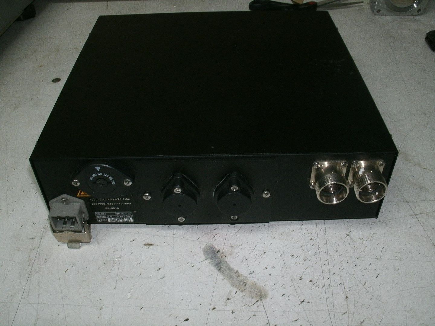
Alright I bought 3 resistors, just incase! I also bought 3 702B exe boxes. With power cords.
The encoders will plug directly into the exe boxes but I'll have to get the output 12 pin male cannon plugs and pins.
Also I'll need to buy a female 10 pin adapter for the cut encoder cable going to the servo. That way I can re-wire the encoder as the factory.
The encoders will plug directly into the exe boxes but I'll have to get the output 12 pin male cannon plugs and pins.
Also I'll need to buy a female 10 pin adapter for the cut encoder cable going to the servo. That way I can re-wire the encoder as the factory.
Last edit: 12 Dec 2015 22:39 by cncnoob1979.
Please Log in or Create an account to join the conversation.
- andypugh
-
- Offline
- Moderator
-
Less
More
- Posts: 19875
- Thank you received: 4642
12 Dec 2015 23:08 #66900
by andypugh
Are they Cannon or M23?
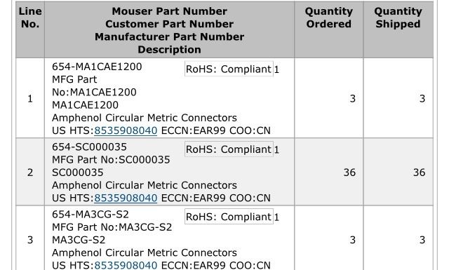
For M23 I found that Mouser were cheaper by a margin:
eu.mouser.com/ProductDetail/Amphenol-SIN...F7csqVWi750vPlnOM%3d
Note that these connectors need a backshell chosen to suit the cable, too.
Replied by andypugh on topic Planning - Bridgeport Interact 1 linuxCNC Retrofit
The encoders will plug directly into the exe boxes but I'll have to get the output 12 pin male cannon plugs and pins.
Are they Cannon or M23?
For M23 I found that Mouser were cheaper by a margin:
eu.mouser.com/ProductDetail/Amphenol-SIN...F7csqVWi750vPlnOM%3d
Note that these connectors need a backshell chosen to suit the cable, too.
Please Log in or Create an account to join the conversation.
- cncnoob1979
-
Topic Author
- Offline
- Platinum Member
-
Less
More
- Posts: 403
- Thank you received: 75
12 Dec 2015 23:58 - 13 Dec 2015 03:46 #66906
by cncnoob1979
Replied by cncnoob1979 on topic Planning - Bridgeport Interact 1 linuxCNC Retrofit
Yes you are correct. They are 12-pin
M23 flange socket. I'll look into the back-shell selections.
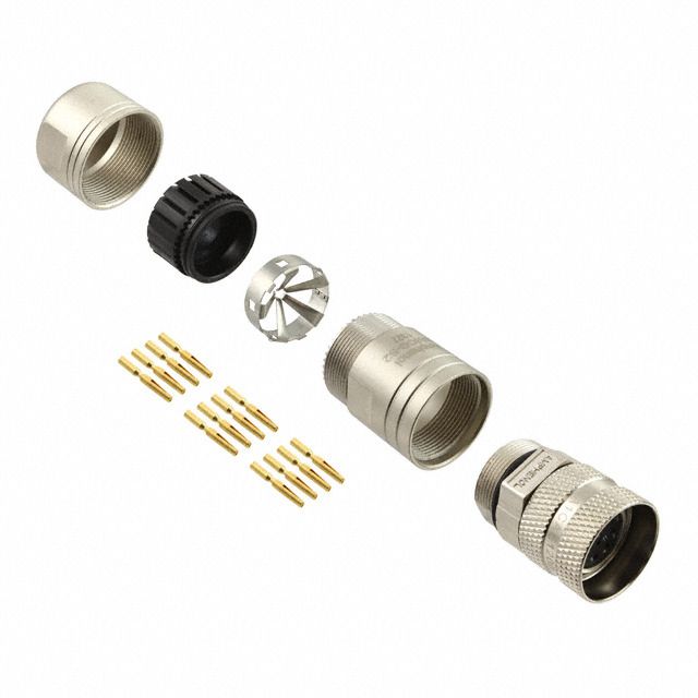
I found these here: MA1CAE1200 KIT
Are these male contacts or are these female contacts? (PINS?) Or do I need to order the pins separately? I'm a bit confused by all the options.
I'm used to solid pins, looking at these it appears the pins are split and I assume are pushed into the female receptacle of the EXE box. Am, I correct in my assumption? That what is shown in the image is a male pin, split and the solid female portion is for wire crimp?
Thanks for the help and the responses! You have helped me a lot so far.
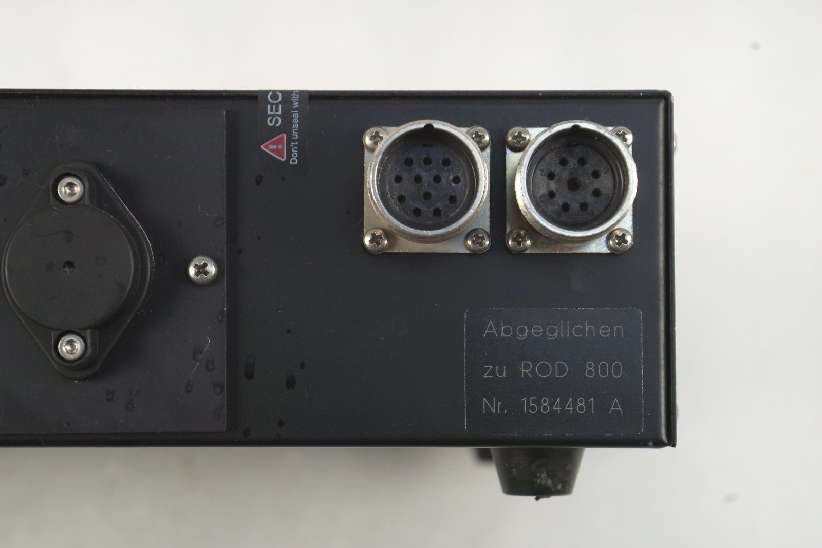
These connectors are threaded and it appears that the output *from the pic - the connector on the left*, is reversed numbered *counter clockwise*, I don't know about the threading however.
M23 flange socket. I'll look into the back-shell selections.
I found these here: MA1CAE1200 KIT
Are these male contacts or are these female contacts? (PINS?) Or do I need to order the pins separately? I'm a bit confused by all the options.
I'm used to solid pins, looking at these it appears the pins are split and I assume are pushed into the female receptacle of the EXE box. Am, I correct in my assumption? That what is shown in the image is a male pin, split and the solid female portion is for wire crimp?

Thanks for the help and the responses! You have helped me a lot so far.


These connectors are threaded and it appears that the output *from the pic - the connector on the left*, is reversed numbered *counter clockwise*, I don't know about the threading however.
Last edit: 13 Dec 2015 03:46 by cncnoob1979.
Please Log in or Create an account to join the conversation.
- cncnoob1979
-
Topic Author
- Offline
- Platinum Member
-
Less
More
- Posts: 403
- Thank you received: 75
13 Dec 2015 22:38 #66931
by cncnoob1979
Replied by cncnoob1979 on topic Planning - Bridgeport Interact 1 linuxCNC Retrofit
I applied 24v to CR13 for the y axis (#85) enable and manually actuated CF5 to apply power to my Amps, then I used an AA battery for the command voltage (#45/#46) and it WORKS! 
Now I need to test the other axis's. The transformers are loud and something about 600v makes me cringe when I have my hands in the control cabinet!")
I'm still trying to figure out if I have a 24v power source going to the original control. I know I have AC for the TCN-151 wiring, so since I haven't found a 24v source In the original controllers wiring, I assume the original control converted and passed 24v internally to drive the relays.
Is that correct?
Now I need to test the other axis's. The transformers are loud and something about 600v makes me cringe when I have my hands in the control cabinet!
I'm still trying to figure out if I have a 24v power source going to the original control. I know I have AC for the TCN-151 wiring, so since I haven't found a 24v source In the original controllers wiring, I assume the original control converted and passed 24v internally to drive the relays.
Is that correct?
Please Log in or Create an account to join the conversation.
- andypugh
-
- Offline
- Moderator
-
Less
More
- Posts: 19875
- Thank you received: 4642
14 Dec 2015 00:06 #66933
by andypugh
Those are the female receptacles.
You can see the pins here:
www.digikey.com/product-detail/en/MA1LAP.../889-1259-ND/4415043
You need the same thing but differently gendered. A phone call to Amphenol or Digikey might be the expedient solution.
[quote[These connectors are threaded and it appears that the output *from the pic - the connector on the left*, is reversed numbered *counter clockwise*, I don't know about the threading however.[/quote]
In any circular connector, one half will be numbered clockwise, and one anticlockwise. I know this because I have messed it up enough times to learn the lesson.
Replied by andypugh on topic Planning - Bridgeport Interact 1 linuxCNC Retrofit
Are these male contacts or are these female contacts? (PINS?) Or do I need to order the pins separately? I'm a bit confused by all the options.
Those are the female receptacles.
You can see the pins here:
www.digikey.com/product-detail/en/MA1LAP.../889-1259-ND/4415043
You need the same thing but differently gendered. A phone call to Amphenol or Digikey might be the expedient solution.
[quote[These connectors are threaded and it appears that the output *from the pic - the connector on the left*, is reversed numbered *counter clockwise*, I don't know about the threading however.[/quote]
In any circular connector, one half will be numbered clockwise, and one anticlockwise. I know this because I have messed it up enough times to learn the lesson.
Please Log in or Create an account to join the conversation.
- andypugh
-
- Offline
- Moderator
-
Less
More
- Posts: 19875
- Thank you received: 4642
14 Dec 2015 00:11 #66935
by andypugh
That's good news.
Looking at the wiring diagram there is a 24V supply from TR1. Do you still have TR1?
Replied by andypugh on topic Planning - Bridgeport Interact 1 linuxCNC Retrofit
I applied 24v to CR13 for the y axis (#85) enable and manually actuated CF5 to apply power to my Amps, then I used an AA battery for the command voltage (#45/#46) and it WORKS!
That's good news.
I'm still trying to figure out if I have a 24v power source going to the original control.
Looking at the wiring diagram there is a 24V supply from TR1. Do you still have TR1?
Please Log in or Create an account to join the conversation.
- cncnoob1979
-
Topic Author
- Offline
- Platinum Member
-
Less
More
- Posts: 403
- Thank you received: 75
14 Dec 2015 02:18 - 14 Dec 2015 03:57 #66941
by cncnoob1979
Replied by cncnoob1979 on topic Planning - Bridgeport Interact 1 linuxCNC Retrofit
Andy, yes I still have TR1 and I do have 24v from that transformer.
I was trying to figure out if I already had 24v (from T1) wiring from my control cabinet through the swing arm to the original control. But I do not. The 24v signal must have been transformed by the original controller in that area.
I was suspect on the pins. Glad I asked prior to purchase. I'll call tomorrow and order myself three with male pins.
My statement previously about the clockwise and counter clockwise - I was pointing out that the two jacks PIN numbers are different. The right (J2) starts from pin 1 in the 1:00 o'clock position then counts clockwise pin 1-12. However the left Jack (J1) starts at the 11:00 o'clock position and counts counter clockwise pin 1-12.
From reading it seems like it's not a M23 A (E) series, but a M23 A (P) series, speaking of only J1. (From memory)
But if the threads are the same I could care less about pin positions because I'll plug my pins in where I want. I hope I was more clear in this post.
Last edit: 14 Dec 2015 03:57 by cncnoob1979.
Please Log in or Create an account to join the conversation.
- andypugh
-
- Offline
- Moderator
-
Less
More
- Posts: 19875
- Thank you received: 4642
14 Dec 2015 10:30 #66946
by andypugh
There is something slightly funny going on, actually.
www.heidenhain.de/de_EN/php/documentatio...w/file-0299/file.pdf
Shows the encoder cable with pins, and then the EXE outputs as pins.
You have sockets on both. The connector handed-ness switch in the PDF is probably explained by that.
I would suggest poking the pins in the holes without the shell to see what works before committing to pin insertion.
Replied by andypugh on topic Planning - Bridgeport Interact 1 linuxCNC Retrofit
My statement previously about the clockwise and counter clockwise - I was pointing out that the two jacks PIN numbers are different. The right (J2) starts from pin 1 in the 1:00 o'clock position then counts clockwise pin 1-12. However the left Jack (J1) starts at the 11:00 o'clock position and counts counter clockwise pin 1-12.
There is something slightly funny going on, actually.
www.heidenhain.de/de_EN/php/documentatio...w/file-0299/file.pdf
Shows the encoder cable with pins, and then the EXE outputs as pins.
You have sockets on both. The connector handed-ness switch in the PDF is probably explained by that.
I would suggest poking the pins in the holes without the shell to see what works before committing to pin insertion.
Please Log in or Create an account to join the conversation.
- cncnoob1979
-
Topic Author
- Offline
- Platinum Member
-
Less
More
- Posts: 403
- Thank you received: 75
14 Dec 2015 23:42 - 14 Dec 2015 23:44 #66989
by cncnoob1979
Replied by cncnoob1979 on topic Planning - Bridgeport Interact 1 linuxCNC Retrofit
Andy,
I ordered the connectors and back shells with male pins. Now I just need to get some cable.
I think that in practice from the factory with these boxes they use a male adapter. They but two females together and place a male adapter between the two. I saw a box that still had the pin adapter installed. IMO, but I could of course be wrong.
I'll have to figure out how many wires and proper shielding for these.
I ordered the connectors and back shells with male pins. Now I just need to get some cable.

I think that in practice from the factory with these boxes they use a male adapter. They but two females together and place a male adapter between the two. I saw a box that still had the pin adapter installed. IMO, but I could of course be wrong.
I'll have to figure out how many wires and proper shielding for these.
Last edit: 14 Dec 2015 23:44 by cncnoob1979.
Please Log in or Create an account to join the conversation.
Time to create page: 0.187 seconds