Planning - Bridgeport Interact 1 linuxCNC Retrofit
- cncnoob1979
-
 Topic Author
- Offline
- Platinum Member
-

Less
More
- Posts: 403
- Thank you received: 75
22 Dec 2015 17:09 - 22 Dec 2015 17:15 #67241
by cncnoob1979
Replied by cncnoob1979 on topic Planning - Bridgeport Interact 1 linuxCNC Retrofit
Hey BigJohnT!
Yeah I tried to clean one of the orifice's but then it stuck! I assume removing the lubrication from the floating pin in the orifice caused it to stick. I just oiled it again and put some pressure behind it [pushing down on the lube handle] and now seems that it is flowing the same as the rest on the table.
Also, as a note to others reading this, be careful pushing down on the Bijur handle to pressurize the oil system. I blew a connection in the knee under the y axis covers. That was a pain to get back together!
I have attached some pictures of the manifolds of this mill.
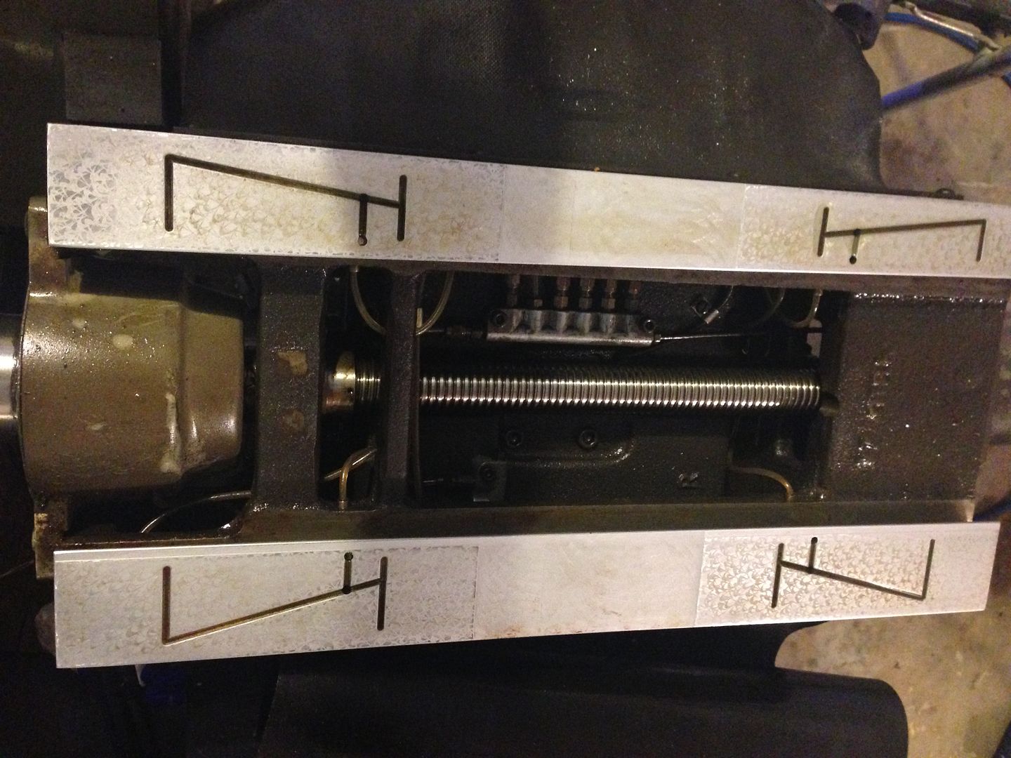
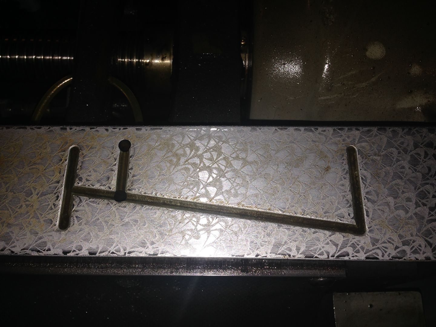
Im trying to find a place to order a few spare 00, 0 and 1's for spares. When I pressurized the oil system as stated above I got drops from the 00, on the quill. The picture is while I was troubleshooting the oil system. I now have even oil flow from each orifice on the table.
I think its now clear. Also, I have cleaned the table and the galleys that have been cut into the table and gib.
Also: as a side note my 702B EXE boxes came in and I will be building cables for the output to the 7i77 cards using the M25 connectors as Andy and I have talked about. I will be using CAT5, or CAT6 cable. Any suggestions? Recommendations?
Last edit: 22 Dec 2015 17:15 by cncnoob1979.
Please Log in or Create an account to join the conversation.
- Todd Zuercher
-

- Away
- Platinum Member
-
Less
More
- Posts: 4757
- Thank you received: 1459
22 Dec 2015 17:17 #67242
by Todd Zuercher
Replied by Todd Zuercher on topic Planning - Bridgeport Interact 1 linuxCNC Retrofit
McMaster Carr has them.
www.mcmaster.com/#oil-lubrication-systems/=10cnrf5
www.mcmaster.com/#oil-lubrication-systems/=10cnrf5
Please Log in or Create an account to join the conversation.
- cncnoob1979
-
Topic Author
- Offline
- Platinum Member
-
Less
More
- Posts: 403
- Thank you received: 75
22 Dec 2015 17:45 #67243
by cncnoob1979
Replied by cncnoob1979 on topic Planning - Bridgeport Interact 1 linuxCNC Retrofit
Awesome!
Thanks Todd! You rock.
Thanks Todd! You rock.
Please Log in or Create an account to join the conversation.
- cncnoob1979
-
Topic Author
- Offline
- Platinum Member
-
Less
More
- Posts: 403
- Thank you received: 75
27 Dec 2015 18:45 #67377
by cncnoob1979
Replied by cncnoob1979 on topic Planning - Bridgeport Interact 1 linuxCNC Retrofit
Ok, purchased a 5i25 and a 6i25/7i77 to go kit. Had to purchase this way for a 5i25/7i77 combo. These were my only options because that is what Mesa had in stock. I'll be future proof with a 6i25 card either way.
I got my mill table back on and I can really tell the difference with proper oiling. I'll be glad when I get started putting things together.
I'll need an external 5v source. Any recommendations for a transformer?
I've been looking at a few buck dc-dc step downs with the displayed voltmeter.
Also I'm looking at 5HP VFD's I'm thinking about the cheap China ones due to price. They state with MODBUS I could close the loop using a spindle encoder.
Please Log in or Create an account to join the conversation.
- kornphlake79
- Offline
- Senior Member
-

Less
More
- Posts: 52
- Thank you received: 10
28 Dec 2015 06:23 - 28 Dec 2015 06:24 #67388
by kornphlake79
Replied by kornphlake79 on topic Planning - Bridgeport Interact 1 linuxCNC Retrofit
Automationdirect.com has great prices, phone support excellent documentation and a warranty on their vfds, for just a little more than cheap units on ebay. They offer free 2 day shipping too. Unless you need high accuracy on the spindle speed for some reason I would just enter the parameters for quick setup on the drive and run it without feedback, whenever I have checked a motor with an optical tach it has been within a few percent of the commanded speed as long as I have entered the correct parameters.
I use automation direct for just about all my automation supplies, they cant be beat on pneumatic push to connect fittings and tubing, I have had good luck with their pneumatic valves as well, their direct logic PLCs are well known for value.
I use automation direct for just about all my automation supplies, they cant be beat on pneumatic push to connect fittings and tubing, I have had good luck with their pneumatic valves as well, their direct logic PLCs are well known for value.
Last edit: 28 Dec 2015 06:24 by kornphlake79.
Please Log in or Create an account to join the conversation.
- andypugh
-

- Offline
- Moderator
-

Less
More
- Posts: 19875
- Thank you received: 4642
28 Dec 2015 23:03 #67421
by andypugh
Those are cheap and give useful feedback. I like them.
Replied by andypugh on topic Planning - Bridgeport Interact 1 linuxCNC Retrofit
I'll need an external 5v source. Any recommendations for a transformer?
I've been looking at a few buck dc-dc step downs with the displayed voltmeter.
Those are cheap and give useful feedback. I like them.
Please Log in or Create an account to join the conversation.
- cncnoob1979
-
Topic Author
- Offline
- Platinum Member
-
Less
More
- Posts: 403
- Thank you received: 75
02 Jan 2016 02:57 - 02 Jan 2016 03:49 #67680
by cncnoob1979
Replied by cncnoob1979 on topic Planning - Bridgeport Interact 1 linuxCNC Retrofit
Yes I think I'll get one of the cheap China VFD's 5hp single phase. Also I'll probably be getting a cheap Buck DC step down.
But now I have a more immediate issue.
I just ran 120v to my 24v system! Blowing my resistor on my "bread board" and taking out my CFU1 fuse, good thing those blew, but I might have taken out a 24v relay or two. Not sure yet.
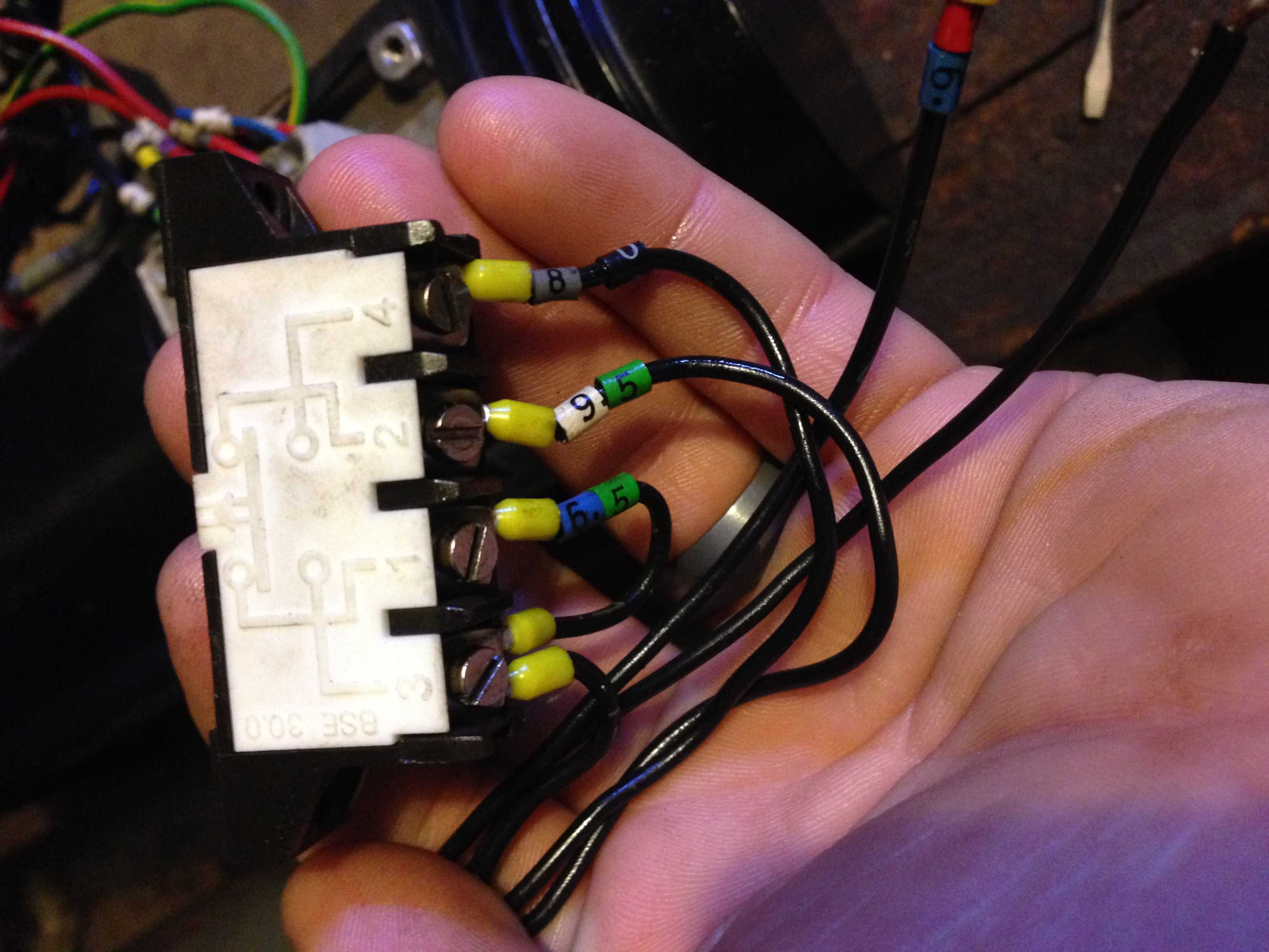
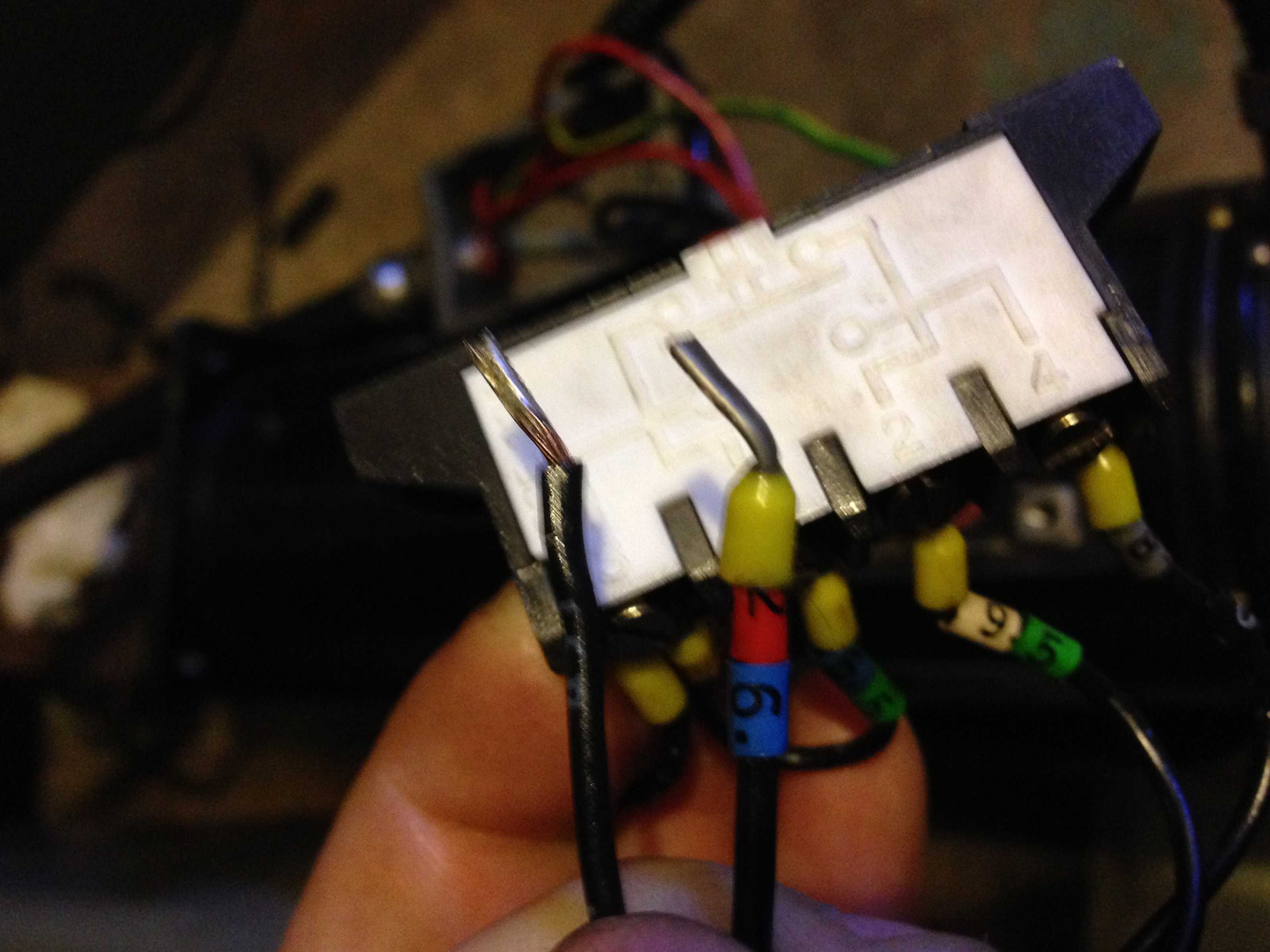
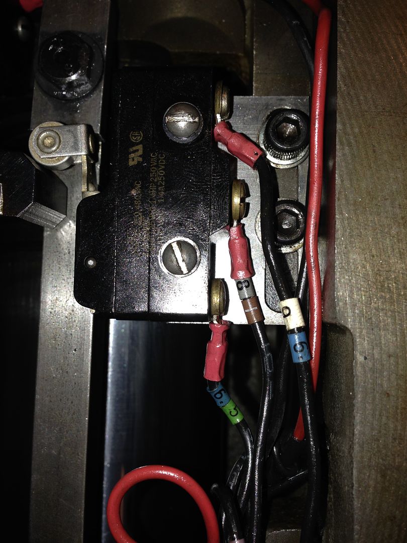
My "y" axis limit switch was partially dissembled. Wire# 26, and a unmarked wire going to my "z" axis upper limit switch, Those two had 120v. I HAVE not made any changes on this limit switch since I received this machine. The way I connected these wires was to #26 to 95 and the unmarked [#25?] to 65. [Limit switch pin 1 and 2] I guess you can now say I know I was wrong
Im guessing I had 24v going through wire #95. And the way the switch is wired I did not realize I had 24v on the other side of the switch. I need 110v to pass through my limits for the joystick. I tested this by just connecting my #26 and the unmarked wire together. Voltmeter had 120v on each wire, prior to me connecting them. (I had my enable on a on/off switch) after connecting them I could "turn off my enable switch" and use it as a momentary switch as designed.
I was correct that it was what I needed. However I screwed up my wiring in my "y" limit switch box.
I sure could use the help figuring this wiring out of my limit switch.
Here are some attached photos.
But now I have a more immediate issue.
I just ran 120v to my 24v system!
Blowing my resistor on my "bread board" and taking out my CFU1 fuse, good thing those blew, but I might have taken out a 24v relay or two. Not sure yet.My "y" axis limit switch was partially dissembled. Wire# 26, and a unmarked wire going to my "z" axis upper limit switch, Those two had 120v. I HAVE not made any changes on this limit switch since I received this machine. The way I connected these wires was to #26 to 95 and the unmarked [#25?] to 65. [Limit switch pin 1 and 2] I guess you can now say I know I was wrong
Im guessing I had 24v going through wire #95. And the way the switch is wired I did not realize I had 24v on the other side of the switch. I need 110v to pass through my limits for the joystick. I tested this by just connecting my #26 and the unmarked wire together. Voltmeter had 120v on each wire, prior to me connecting them. (I had my enable on a on/off switch) after connecting them I could "turn off my enable switch" and use it as a momentary switch as designed.
I was correct that it was what I needed. However I screwed up my wiring in my "y" limit switch box.
I sure could use the help figuring this wiring out of my limit switch.
Here are some attached photos.
Last edit: 02 Jan 2016 03:49 by cncnoob1979.
Please Log in or Create an account to join the conversation.
- cncnoob1979
-
Topic Author
- Offline
- Platinum Member
-
Less
More
- Posts: 403
- Thank you received: 75
02 Jan 2016 03:16 - 02 Jan 2016 04:13 #67683
by cncnoob1979
Replied by cncnoob1979 on topic Planning - Bridgeport Interact 1 linuxCNC Retrofit
I removed the blown resistor located on the 2nd leg from the top. Anyone can you tell what size it is? Looks gold, black, black, brown. I'll check the tables for the 4 banded resistors and see if it makes sense. [Edit: its a 10 Ohms 5%, Watt's unknown] suggestions?]
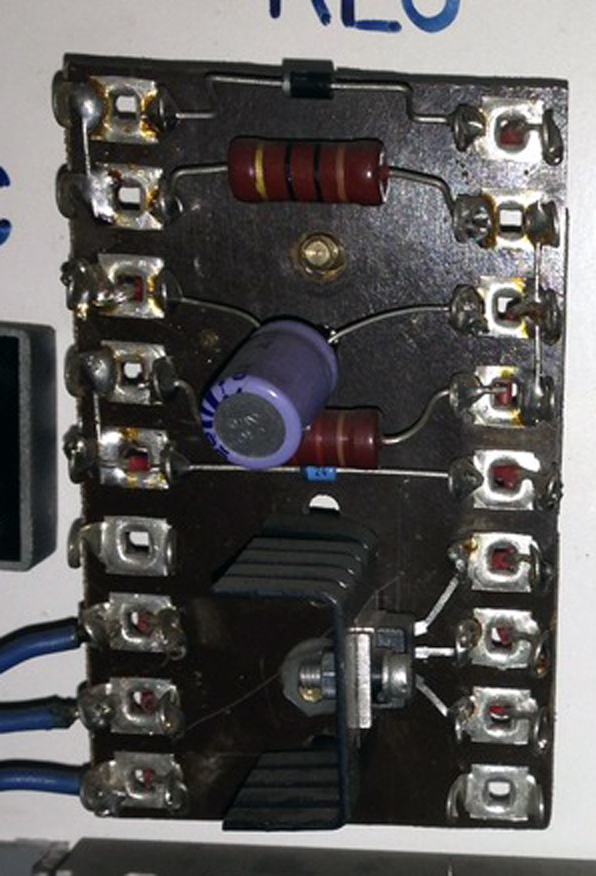
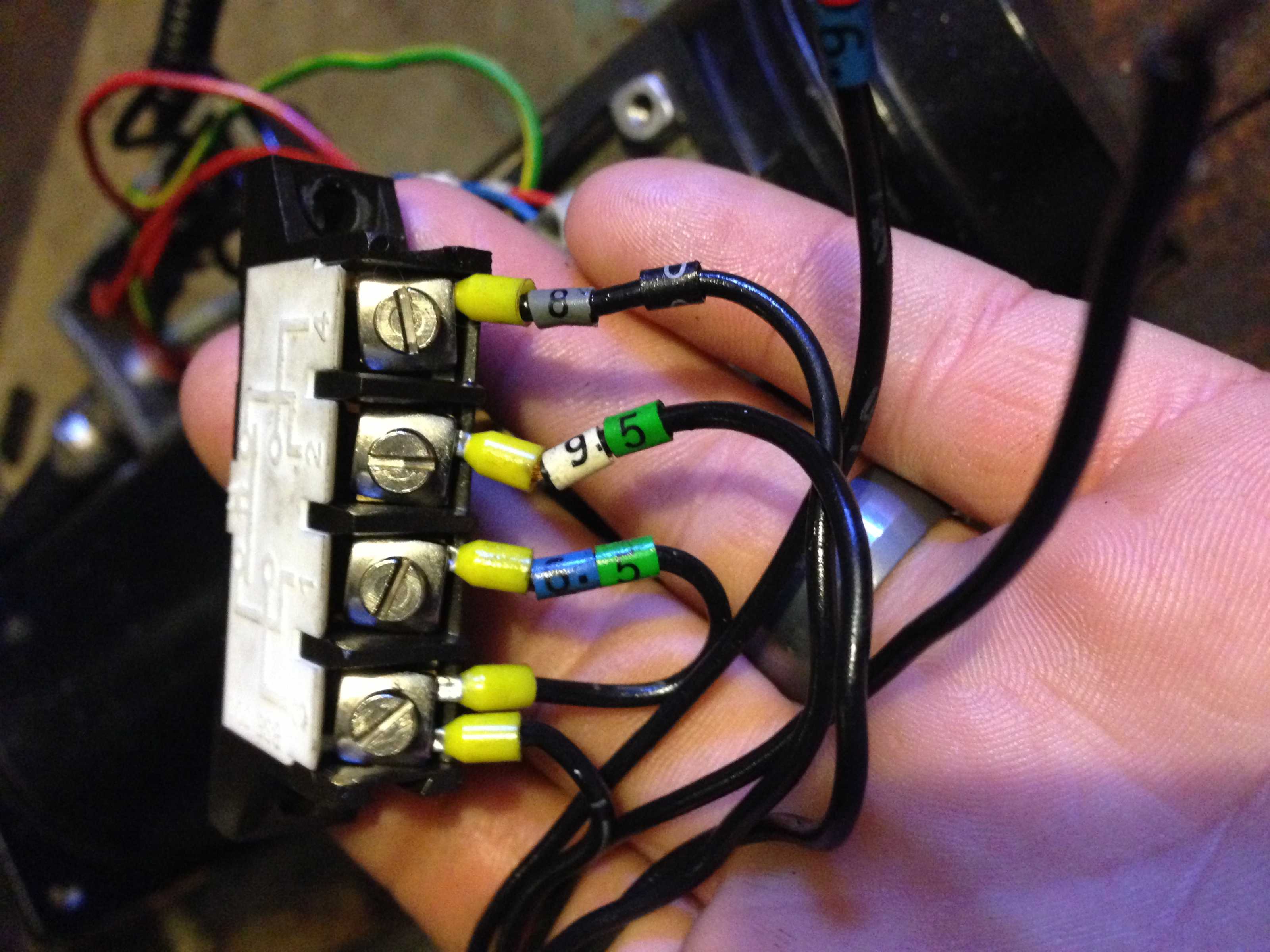
The lower wire #65 is where i ran my wire out. I made the mistake of not disconnecting it first. Perhaps I missed something, or I was connected elsewhere. I'm going to disconnect it an try to ring it again, to figure out the unmarked wire number.
I attached a highlighted wiring diagram of what I blew and connected. "blown.pdf"

After further studying the schematics I think I should have just tied these wires together, I don't see how they could be tied into the limit switch. Either way sending 120V into this switch will send 120v into the 24v system. Suggestions are welcome.")
The lower wire #65 is where i ran my wire out. I made the mistake of not disconnecting it first. Perhaps I missed something, or I was connected elsewhere. I'm going to disconnect it an try to ring it again, to figure out the unmarked wire number.

I attached a highlighted wiring diagram of what I blew and connected. "blown.pdf"
After further studying the schematics I think I should have just tied these wires together, I don't see how they could be tied into the limit switch. Either way sending 120V into this switch will send 120v into the 24v system. Suggestions are welcome.
Last edit: 02 Jan 2016 04:13 by cncnoob1979.
Please Log in or Create an account to join the conversation.
- andypugh
-
- Offline
- Moderator
-
Less
More
- Posts: 19875
- Thank you received: 4642
02 Jan 2016 04:31 #67685
by andypugh
Well, given that resistor cost is minimal, just assume it dissipates all it can at the applied voltage.
P = V2/R
So, 120V = 1.4kW
24V = 60W
OK, so don't assume that
It looks like a 5W, but if you can read the bands it might be OK.
Replied by andypugh on topic Planning - Bridgeport Interact 1 linuxCNC Retrofit
I removed the blown resistor located on the 2nd leg from the top. Anyone can you tell what size it is? Looks gold, black, black, brown. I'll check the tables for the 4 banded resistors and see if it makes sense. [Edit: its a 10 Ohms 5%, Watt's unknown] suggestions?]
Well, given that resistor cost is minimal, just assume it dissipates all it can at the applied voltage.
P = V2/R
So, 120V = 1.4kW
24V = 60W
OK, so don't assume that
It looks like a 5W, but if you can read the bands it might be OK.
Please Log in or Create an account to join the conversation.
- kornphlake79
- Offline
- Senior Member
-
Less
More
- Posts: 52
- Thank you received: 10
02 Jan 2016 04:33 - 02 Jan 2016 04:42 #67686
by kornphlake79
Replied by kornphlake79 on topic Planning - Bridgeport Interact 1 linuxCNC Retrofit
In your first picture Terminals 1 and 2 are normally closed contacts and terminals 3 and 4 are normally open. Wire 65 should be common since it's jumpered and wires 95 and 80 would be your signal wires all should carry 24v. These are home switches right? You should have 2 more switches on other axis with wires 94 and 79 and another switch with wires 96 and 81.
The schematic suggests you should have limit switches where wires 23,25, 26, 123, and 27 would be connected carrying 120v signal. There should be 1 limit switch for the x and one for the y axis and 2 on the z axis, in addition to a home switch for each axis. Is this correct? If you don't have limit and home switches on each axis you'll need to figure out what you do have and redraw the schematic. Given this configuration there is no way to use the limit switches as home switches or vice versa without changing some IO hardware
The schematic suggests you should have limit switches where wires 23,25, 26, 123, and 27 would be connected carrying 120v signal. There should be 1 limit switch for the x and one for the y axis and 2 on the z axis, in addition to a home switch for each axis. Is this correct? If you don't have limit and home switches on each axis you'll need to figure out what you do have and redraw the schematic. Given this configuration there is no way to use the limit switches as home switches or vice versa without changing some IO hardware
Last edit: 02 Jan 2016 04:42 by kornphlake79.
Please Log in or Create an account to join the conversation.
Time to create page: 0.336 seconds