Planning - Bridgeport Interact 1 linuxCNC Retrofit
- cncnoob1979
-
 Topic Author
- Offline
- Platinum Member
-

Less
More
- Posts: 403
- Thank you received: 75
02 Jan 2016 04:57 #67687
by cncnoob1979
Replied by cncnoob1979 on topic Planning - Bridgeport Interact 1 linuxCNC Retrofit
Andy,
Yes I'm thinking between 5 watts and 10 for the resistor... or just replace it all with the buck step down transformer. Would be easier to just replace the resistor tho. Cant believe I was such a dummy! lol
kornphlake79,
I'm trying to figure out the wiring on my limit switches now. Each one passes a reference signal as well via 24v and the limits are 120v. Hence the reason I was trying to figure out the y axis before I tried to kill the machine. [Well I guess I did kill it!]
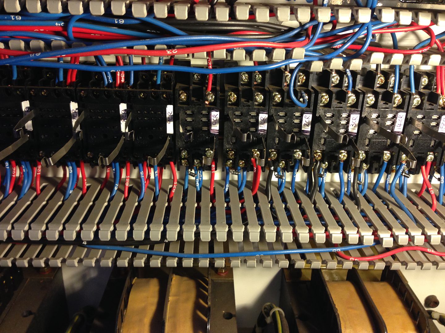
These wires were in this limit switch prior, I'm sure of it. I just don't see how it was wired. The wire #65 should only be carrying 24v current and the two wires not wired in, are 120v, so I'm not sure how I can wire these. However I do believe that someone has taken the limit switch relay from this box. The relay box can carry two switches internally and there is only one installed. I think it was robbed? Not sure yet.
Yes I'm thinking between 5 watts and 10 for the resistor... or just replace it all with the buck step down transformer. Would be easier to just replace the resistor tho. Cant believe I was such a dummy! lol
kornphlake79,
I'm trying to figure out the wiring on my limit switches now. Each one passes a reference signal as well via 24v and the limits are 120v. Hence the reason I was trying to figure out the y axis before I tried to kill the machine. [Well I guess I did kill it!]
These wires were in this limit switch prior, I'm sure of it. I just don't see how it was wired. The wire #65 should only be carrying 24v current and the two wires not wired in, are 120v, so I'm not sure how I can wire these. However I do believe that someone has taken the limit switch relay from this box. The relay box can carry two switches internally and there is only one installed. I think it was robbed? Not sure yet.
Please Log in or Create an account to join the conversation.
- kornphlake79
- Offline
- Senior Member
-

Less
More
- Posts: 52
- Thank you received: 10
02 Jan 2016 05:25 #67688
by kornphlake79
Replied by kornphlake79 on topic Planning - Bridgeport Interact 1 linuxCNC Retrofit
I missed the part about using the VFD to run a 3 phase spindle motor with single phase power. Good luck with that, 5hp is kind of the tipping point where you can or should use a VFD to convert single phase to 3 phase. As a general rule you should derate the capacity of the VFD when converting from 1 to 3 phase, for a 5hp motor your VFD should be rated for 7-10HP 3 phase. The Chinese units may claim to be rated for 5hp and single phase, but there is a reason it's hard to find VFDs with a recognizable name brand rated for single phase at 5hp, and when you do find them there is a reason the VFD cost a couple times more than an equivalent VFD that only operates on 3 phase.
I know people have used the Chinese VFDs and they do work, but I'm not sure for how long, or how well. There is a good chance those inexpensive drives can't supply enough current to the motor to reach the rated capacity. Since your machine has the capability of mechanically varying the spindle speed, you might consider a phase converter and idler motor instead of a VFD, unfortunately that means you'll have to manually adjust the spindle speed, but that's not a huge deal since you'll be manually changing tools anyway.
I know people have used the Chinese VFDs and they do work, but I'm not sure for how long, or how well. There is a good chance those inexpensive drives can't supply enough current to the motor to reach the rated capacity. Since your machine has the capability of mechanically varying the spindle speed, you might consider a phase converter and idler motor instead of a VFD, unfortunately that means you'll have to manually adjust the spindle speed, but that's not a huge deal since you'll be manually changing tools anyway.
Please Log in or Create an account to join the conversation.
- kornphlake79
- Offline
- Senior Member
-
Less
More
- Posts: 52
- Thank you received: 10
02 Jan 2016 05:55 - 02 Jan 2016 06:01 #67690
by kornphlake79
I supervise a maintenance tech who can't read schematics (and tried to convince me that my 2d drawings were wrong because he can't understand 3rd angle projections) and doesn't understand industrial electronics, yet he insists he can troubleshoot and replace switches like this. I'm constantly having to rewire switches that he's "positive" were wired the same as before he started working on it. Most of our equipment uses 24v controls so wiring mistakes have not caused failures like you've experienced, but I did have a transformer and a contactor that were nuked when he put 480v into the 24v control side of an HVAC unit. Afterward he showed me the photo he'd taken before removing any of the wires, and tried to explain that he couldn't have done anything wrong because all the wires went back to the same places they were in the photo, what he didn't notice was that he'd already disconnected one wire before taking the photo, but because of the angle it looked like the wire was connected to a (wrong) terminal. It was obvious to me that he'd put 480v into the coil side of the contactor which made no sense and would have caused very different symptoms than the unit was exhibiting, but he still insists that the wiring was that way before he attempted the repair and the photo supposedly proves it. It's tough to work with people who are always right, they need to realize that I'm always right!
In your situation I would assume my tech worked on your mill before you bought it, if the wiring doesn't match the schematic it is wrong, make it match the schematic or trace the wires end to end and draw your own schematic, and make sure it makes sense before you give anything power. You didn't observe the machine running before you bought it because the control had been removed right? Was the control removed because the wiring was tampered with and the control was damaged as a result?
Replied by kornphlake79 on topic Planning - Bridgeport Interact 1 linuxCNC Retrofit
kornphlake79,
I'm trying to figure out the wiring on my limit switches now. Each one passes a reference signal as well via 24v and the limits are 120v. Hence the reason I was trying to figure out the y axis before I tried to kill the machine. [Well I guess I did kill it!]
These wires were in this limit switch prior, I'm sure of it. I just don't see how it was wired. The wire #65 should only be carrying 24v current and the two wires not wired in, are 120v, so I'm not sure how I can wire these. However I do believe that someone has taken the limit switch relay from this box. The relay box can carry two switches internally and there is only one installed. I think it was robbed? Not sure yet.
I supervise a maintenance tech who can't read schematics (and tried to convince me that my 2d drawings were wrong because he can't understand 3rd angle projections) and doesn't understand industrial electronics, yet he insists he can troubleshoot and replace switches like this. I'm constantly having to rewire switches that he's "positive" were wired the same as before he started working on it. Most of our equipment uses 24v controls so wiring mistakes have not caused failures like you've experienced, but I did have a transformer and a contactor that were nuked when he put 480v into the 24v control side of an HVAC unit. Afterward he showed me the photo he'd taken before removing any of the wires, and tried to explain that he couldn't have done anything wrong because all the wires went back to the same places they were in the photo, what he didn't notice was that he'd already disconnected one wire before taking the photo, but because of the angle it looked like the wire was connected to a (wrong) terminal. It was obvious to me that he'd put 480v into the coil side of the contactor which made no sense and would have caused very different symptoms than the unit was exhibiting, but he still insists that the wiring was that way before he attempted the repair and the photo supposedly proves it. It's tough to work with people who are always right, they need to realize that I'm always right!
In your situation I would assume my tech worked on your mill before you bought it, if the wiring doesn't match the schematic it is wrong, make it match the schematic or trace the wires end to end and draw your own schematic, and make sure it makes sense before you give anything power. You didn't observe the machine running before you bought it because the control had been removed right? Was the control removed because the wiring was tampered with and the control was damaged as a result?
Last edit: 02 Jan 2016 06:01 by kornphlake79.
Please Log in or Create an account to join the conversation.
- cncnoob1979
-
Topic Author
- Offline
- Platinum Member
-
Less
More
- Posts: 403
- Thank you received: 75
02 Jan 2016 06:35 - 02 Jan 2016 08:00 #67692
by cncnoob1979
Replied by cncnoob1979 on topic Planning - Bridgeport Interact 1 linuxCNC Retrofit
kornphlake79,
Turns out the limit switch was removed from the machine for the y axis. I can see rub marks where one was installed previously. The guy I purchased from must have taken parts from the machine and no I did not see it running. However I am a a&p licensed mechanic / power-plant among other things but i should have known better! Either way, that is what happens when you get complacent!
I'm having fun doing this retrofit so it just a hobby for me. However I am learning tons of stuff that I thought wouldn't be as difficult as they have been. In aviation schematics you can see every trace with a proper breakdown of each system. This schematic is more of a block diagram! lol
Either way, it plainly stated 24v and I applied 120V thinking it "must go here" lol
I have a 2hp motor on my mill and am going with a 5hp VFD for that very reason, maybe a 4hp, but the prices are fairly cheap for either.
So far the damaged I cause is:
1 120V realy, CR3 - spindle enable- it was working prior.
1 24v regulator, I temporarily installed 3 x 3.3 linked resistors for 9.9 ohm x 30w and they got very hot in about 30 seconds without a load, the regulator is shot, looks like I'm going to replace it with a buck dc-dc regulator.
I do not have access to 24 volts to test all of the DC relays but so far only one 120v got toasty.
Now i need to buy; due to me")
DC-DC buck regulator
5 amp fast blow glass fuse
1x 120V relay
limit switch relay to mount in the y axis limit assembly. [to replace the removed one]
Still needing to purchase:
1x pico power-supply 160watt for my mini atx motherboard.
1x SSD 64gb
I'm waiting patiently for my Mesa hardware to arrive so I can hopefully get this build going.
Turns out the limit switch was removed from the machine for the y axis. I can see rub marks where one was installed previously. The guy I purchased from must have taken parts from the machine and no I did not see it running. However I am a a&p licensed mechanic / power-plant among other things but i should have known better! Either way, that is what happens when you get complacent!
I'm having fun doing this retrofit so it just a hobby for me. However I am learning tons of stuff that I thought wouldn't be as difficult as they have been. In aviation schematics you can see every trace with a proper breakdown of each system. This schematic is more of a block diagram! lol
Either way, it plainly stated 24v and I applied 120V thinking it "must go here" lol
I have a 2hp motor on my mill and am going with a 5hp VFD for that very reason, maybe a 4hp, but the prices are fairly cheap for either.
So far the damaged I cause is:
1 120V realy, CR3 - spindle enable- it was working prior.
1 24v regulator, I temporarily installed 3 x 3.3 linked resistors for 9.9 ohm x 30w and they got very hot in about 30 seconds without a load, the regulator is shot, looks like I'm going to replace it with a buck dc-dc regulator.
I do not have access to 24 volts to test all of the DC relays but so far only one 120v got toasty.
Now i need to buy; due to me
DC-DC buck regulator
5 amp fast blow glass fuse
1x 120V relay
limit switch relay to mount in the y axis limit assembly. [to replace the removed one]
Still needing to purchase:
1x pico power-supply 160watt for my mini atx motherboard.
1x SSD 64gb
I'm waiting patiently for my Mesa hardware to arrive so I can hopefully get this build going.
Last edit: 02 Jan 2016 08:00 by cncnoob1979.
Please Log in or Create an account to join the conversation.
- kornphlake79
- Offline
- Senior Member
-
Less
More
- Posts: 52
- Thank you received: 10
02 Jan 2016 07:53 #67693
by kornphlake79
Replied by kornphlake79 on topic Planning - Bridgeport Interact 1 linuxCNC Retrofit
It is interesting how different industries have different definitions of what is acceptable for documentation. I currently work in consumer goods manufacturing, the schematic you have is pretty typical, somewhat better than a lot of the schematics I have to deal with actually. Previously I worked for a manufacturer of oil and gas equipment and we supplied electrical schematics, full point to point wiring diagrams and logic diagrams. There was very little troubleshooting that couldn't be done with only the wiring diagram, but the other documentation was there if needed. It was a shock for me moving from one industry to another and finding that while I have the competence to do my job, I don't always have the resources to do jobs as efficiently as possible.
Please Log in or Create an account to join the conversation.
- BigJohnT
-

- Offline
- Administrator
-

Less
More
- Posts: 3990
- Thank you received: 994
02 Jan 2016 11:49 #67699
by BigJohnT
You might want to take a look at the Automation Direct GS2 3hp drive with braking resistor, filter and modbus cable. You plug it into your serial port and control it with the gs2 component in LinuxCNC. If you can add an encoder to your spindle then you have rigid tapping.
gnipsel.com/images/bp-knee-mill/encoder07.jpg
gnipsel.com/images/bp-knee-mill/bpel02.jpg
JT
Replied by BigJohnT on topic Planning - Bridgeport Interact 1 linuxCNC Retrofit
kornphlake79,
I have a 2hp motor on my mill and am going with a 5hp VFD for that very reason, maybe a 4hp, but the prices are fairly cheap for either.
You might want to take a look at the Automation Direct GS2 3hp drive with braking resistor, filter and modbus cable. You plug it into your serial port and control it with the gs2 component in LinuxCNC. If you can add an encoder to your spindle then you have rigid tapping.
gnipsel.com/images/bp-knee-mill/encoder07.jpg
gnipsel.com/images/bp-knee-mill/bpel02.jpg
JT
Please Log in or Create an account to join the conversation.
- TntSalad
-

- Offline
- New Member
-

Less
More
- Posts: 10
- Thank you received: 0
03 Jan 2016 07:12 - 03 Jan 2016 07:12 #67743
by TntSalad
Replied by TntSalad on topic Planning - Bridgeport Interact 1 linuxCNC Retrofit
Hey, cncnoob1979,
I kind of read through your post, wrapping up a Bridgeport 300 retrofit with a 5i25/7i77 on residential single phase, just working minor issues out. Looks very similar to the route that you are on. Message me if you have questions, would be glad to help out.
Artyom
I kind of read through your post, wrapping up a Bridgeport 300 retrofit with a 5i25/7i77 on residential single phase, just working minor issues out. Looks very similar to the route that you are on. Message me if you have questions, would be glad to help out.
Artyom
Last edit: 03 Jan 2016 07:12 by TntSalad.
Please Log in or Create an account to join the conversation.
- cncnoob1979
-
Topic Author
- Offline
- Platinum Member
-
Less
More
- Posts: 403
- Thank you received: 75
03 Jan 2016 21:16 - 03 Jan 2016 21:34 #67777
by cncnoob1979
Replied by cncnoob1979 on topic Planning - Bridgeport Interact 1 linuxCNC Retrofit
TntSalad,
Thanks for the offer, I'm sure Ill be reaching out to you soon when I get my hardware from Mesa. So how do you like the VMC?
JT,
Looking at the G2 VFD drives they are very appealing, but looks like around 400~ bucks for the setup. The Chinese VFD's are around 160~ shipped. When I get to the VFD's Ill see where that leaves the "Mill Fund" the wife has been tracking like a hawk! lol
So far, I have bought all new relays ( 7x AC, 7x DC part numbers below), will be a nice upgrade - Now I can see when one is activated. These come with LED indicators [red AC / Green DC] and diodes / snubbers and the ac ones have push tests on them. )
Cost around 50~ for the relays and I also purchased another limit switch wiring block for the one that was removed. You, remember right? The 120v wiring I used to fry my entire 24v system, lol

I also ordered 2x all hardware need to rebuild the 24v regulator so If I mess up I get another shot! 15~ from Mouser. I fried my Zener diode 24v and that took out my resistors and ... well you get the idea... "FIRE FIRE, oh boy"
So that leaves a question, All my DC relays have diodes wired into the mounting base of the relays, It wouldn't hurt to just leave them there would it? Or should I removed them since they are now mounted inside of the relays?

Limt Switch: BALLUFF BSE 30.0-RK Micro Snap Switch BSE300RKAC : OMRON MY4IN-AC110/120(S)DC: Omron LY2N-D2 Relays 24VDC
Last edit: 03 Jan 2016 21:34 by cncnoob1979.
Please Log in or Create an account to join the conversation.
- TntSalad
-
- Offline
- New Member
-
Less
More
- Posts: 10
- Thank you received: 0
03 Jan 2016 21:41 - 03 Jan 2016 22:25 #67780
by TntSalad
Replied by TntSalad on topic Planning - Bridgeport Interact 1 linuxCNC Retrofit
It's great, really happy with everything.
I'd like to pitch in on the VFD and second the chinese drive route.
My motor is a 330V, my line is 230-ish, I didn't want to deal with step up converters or rotary phase converters, didn't have the money for it either. Everything else on machine was pretty straightforward, because only two legs of 3 phase are used for transformers and motor amps. Since I am never planning on running the machine full blast production, I was ok with losing some top end on spindle, but wanted to keep the low end torque.
V/Hz is a pretty common way to get what you are looking for out of the motor, so I got a 2.2kW 220V HY drive off ebay and adjusted the settings for V/Hz curve and max current, so far seems to be doing just fine for feeds I am working at.
Last edit: 03 Jan 2016 22:25 by TntSalad. Reason: Can't spell. I am a hooked on phonics dropout.
Please Log in or Create an account to join the conversation.
- andypugh
-

- Offline
- Moderator
-

Less
More
- Posts: 19875
- Thank you received: 4642
04 Jan 2016 14:10 #67826
by andypugh
You might as well leave them there as backup in case the pixies steal the ones in the relays.
Replied by andypugh on topic Planning - Bridgeport Interact 1 linuxCNC Retrofit
So that leaves a question, All my DC relays have diodes wired into the mounting base of the relays, It wouldn't hurt to just leave them there would it? Or should I removed them since they are now mounted inside of the relays?
You might as well leave them there as backup in case the pixies steal the ones in the relays.
Please Log in or Create an account to join the conversation.
Time to create page: 0.737 seconds