Planning - Bridgeport Interact 1 linuxCNC Retrofit
- cncnoob1979
-
 Topic Author
- Offline
- Platinum Member
-

Less
More
- Posts: 403
- Thank you received: 75
13 Jan 2016 00:11 - 13 Jan 2016 01:09 #68275
by cncnoob1979
Replied by cncnoob1979 on topic Planning - Bridgeport Interact 1 linuxCNC Retrofit
Hey great news. I got the enables working on a test. I connected it as I last described from --Todd -and- it's working.
Thanks for every one helping me understand how to make this work!
My next question is :
can I create a jumper coming from field power using the unused pins to connect to the enable + pin? Or do I need to run sourcing power directly from my 24v system to them each individually?
I'm powering the 7i77 field power from the same 24v supply.
Basically I'm wanting to use the VFIELD 3 unused pins as a 24v terminal block, to power my enable switches.
Last edit: 13 Jan 2016 01:09 by cncnoob1979.
Please Log in or Create an account to join the conversation.
- Todd Zuercher
-

- Away
- Platinum Member
-
Less
More
- Posts: 4757
- Thank you received: 1459
13 Jan 2016 02:06 #68278
by Todd Zuercher
If I understood the question correctly. Yes. I think one of the main reasons for the extra field power connections on the 7i77 is for you to use them for this purpose of routing field power to things like your ENA+ connector.
Replied by Todd Zuercher on topic Planning - Bridgeport Interact 1 linuxCNC Retrofit
Hey great news. I got the enables working on a test. I connected it as I last described from --Todd -and- it's working.
Thanks for every one helping me understand how to make this work!
My next question is :
can I create a jumper coming from field power using the unused pins to connect to the enable + pin? Or do I need to run sourcing power directly from my 24v system to them each individually?
I'm powering the 7i77 field power from the same 24v supply.
Basically I'm wanting to use the VFIELD 3 unused pins as a 24v terminal block, to power my enable switches.
If I understood the question correctly. Yes. I think one of the main reasons for the extra field power connections on the 7i77 is for you to use them for this purpose of routing field power to things like your ENA+ connector.
The following user(s) said Thank You: cncnoob1979
Please Log in or Create an account to join the conversation.
- cncnoob1979
-
Topic Author
- Offline
- Platinum Member
-
Less
More
- Posts: 403
- Thank you received: 75
13 Jan 2016 03:28 - 13 Jan 2016 03:28 #68281
by cncnoob1979
Well after a few hours testing all I need todo now is wire up an encoder from the 702B EXE box.
I was [/-----/ ]this close to cutting an hdmi cable. But I need to just order some cable. I think I'll just grab some CAT6e cable and test it.
Thanks guys, yeah I ask some silly questions sometimes but you help me out anyway!
Getting closer, I have run/stop limits and this is all starting to make sense to me now!
Replied by cncnoob1979 on topic Planning - Bridgeport Interact 1 linuxCNC Retrofit


Well after a few hours testing all I need todo now is wire up an encoder from the 702B EXE box.
I was [/-----/ ]this close to cutting an hdmi cable. But I need to just order some cable. I think I'll just grab some CAT6e cable and test it.
Thanks guys, yeah I ask some silly questions sometimes but you help me out anyway!
Getting closer, I have run/stop limits and this is all starting to make sense to me now!
Last edit: 13 Jan 2016 03:28 by cncnoob1979.
Please Log in or Create an account to join the conversation.
- csbrady
- Offline
- Senior Member
-

Less
More
- Posts: 72
- Thank you received: 10
13 Jan 2016 04:15 #68283
by csbrady
Replied by csbrady on topic Planning - Bridgeport Interact 1 linuxCNC Retrofit
If you use cat5 or cat6 (no advantage to using cat6 BTW) then you need to give some thought as to which wires to use. Cat5/6 has 8 twisted pairs. For the differential signals use a pair for the plus and minus signals. Pairs are the same color but one wire will be predominantly white. This will be the A, B and Index signals. You will have a number of unused wires so be sure that the unused wires are connected to ground on one end. Not being shielded should not be a problem as long as the run is fairly short.
Please Log in or Create an account to join the conversation.
- andypugh
-

- Offline
- Moderator
-

Less
More
- Posts: 19875
- Thank you received: 4642
13 Jan 2016 10:03 #68295
by andypugh
I think that CAT5 will work just fine, but you can buy dedicated encoder cable:
www.rapidonline.com/pdf/604159_da_en_01.pdf
I found some on eBay at a reasonable price.
Replied by andypugh on topic Planning - Bridgeport Interact 1 linuxCNC Retrofit
I was [/-----/ ]this close to cutting an hdmi cable. But I need to just order some cable. I think I'll just grab some CAT6e cable and test it.
I think that CAT5 will work just fine, but you can buy dedicated encoder cable:
www.rapidonline.com/pdf/604159_da_en_01.pdf
I found some on eBay at a reasonable price.
Please Log in or Create an account to join the conversation.
- cncnoob1979
-
Topic Author
- Offline
- Platinum Member
-
Less
More
- Posts: 403
- Thank you received: 75
14 Jan 2016 00:15 - 14 Jan 2016 14:49 #68337
by cncnoob1979
Ok I'm using cat5 cable for one 702B exe box. But ran into a snag.
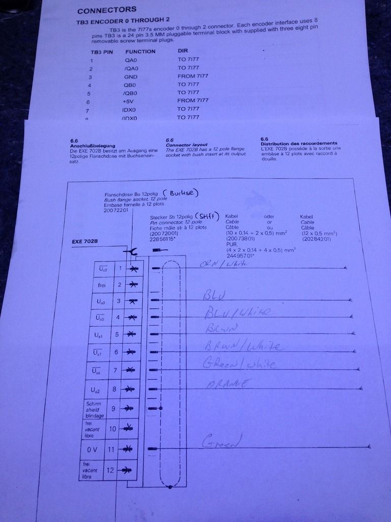
The 7i77 pin outs don't match my EXE box. I have these as attached.
The 7i77 is listed with:
QA0
QB0
IDX
GND assuming same as 0volt
My box doesn't seem to need the 5Volt so I'll try omitting it.
But my EXE is;
A0
A1
A2
As
0V
Anyone know where I can read to match up for certain where each go to the 7i77?
I'm not sure what each signal means besides the GND/0V.
Just guessing but I would assume:
A0 -A0
GND-0V
B0-A2
IDX-AS
??
EDIT:
Ok, I can see A & B TTL signals, not sure from which pins, A1 = A phase and A2 = B phase. I believe because I'm not sure what the 7i77 Pin-out is expecting. On the 7i77 I have wired [a0 = QA0], [a1 = QB0] and [a2 = IDX].
I can not see an index pulse from the encoder, so I expect I have this setup wrong. I also have switched around the wiring numerous times, so now I'm not sure how I have it wired now that I'm at work! lol
I really need to know what the 7i77 encoder pin-outs are expecting. I'm thinking this:
Qa0= A phase TTL
Qb0= B phase TTL
IDX= Index pulse
Then I need to figure out what my signals are from my exe box. After work I plan on just connecting each set / one at a time and look at it from HAL scope and see what it produces. As wired at the moment, I can see the TTL signals, but my velocity and encoder position doesn't seem correct.
Position only moves one direction - even when I turn it by hand
Replied by cncnoob1979 on topic Planning - Bridgeport Interact 1 linuxCNC Retrofit

Ok I'm using cat5 cable for one 702B exe box. But ran into a snag.
The 7i77 pin outs don't match my EXE box. I have these as attached.
The 7i77 is listed with:
QA0
QB0
IDX
GND assuming same as 0volt
My box doesn't seem to need the 5Volt so I'll try omitting it.
But my EXE is;
A0
A1
A2
As
0V
Anyone know where I can read to match up for certain where each go to the 7i77?
I'm not sure what each signal means besides the GND/0V.
Just guessing but I would assume:
A0 -A0
GND-0V
B0-A2
IDX-AS
??
EDIT:
Ok, I can see A & B TTL signals, not sure from which pins, A1 = A phase and A2 = B phase. I believe because I'm not sure what the 7i77 Pin-out is expecting. On the 7i77 I have wired [a0 = QA0], [a1 = QB0] and [a2 = IDX].
I can not see an index pulse from the encoder, so I expect I have this setup wrong. I also have switched around the wiring numerous times, so now I'm not sure how I have it wired now that I'm at work! lol
I really need to know what the 7i77 encoder pin-outs are expecting. I'm thinking this:
Qa0= A phase TTL
Qb0= B phase TTL
IDX= Index pulse
Then I need to figure out what my signals are from my exe box. After work I plan on just connecting each set / one at a time and look at it from HAL scope and see what it produces. As wired at the moment, I can see the TTL signals, but my velocity and encoder position doesn't seem correct.
Position only moves one direction - even when I turn it by hand
Last edit: 14 Jan 2016 14:49 by cncnoob1979.
Please Log in or Create an account to join the conversation.
- andypugh
-
- Offline
- Moderator
-
Less
More
- Posts: 19875
- Thank you received: 4642
14 Jan 2016 15:50 #68381
by andypugh
Replied by andypugh on topic Planning - Bridgeport Interact 1 linuxCNC Retrofit
Do you have a halscope shot?
Please Log in or Create an account to join the conversation.
- cncnoob1979
-
Topic Author
- Offline
- Platinum Member
-
Less
More
- Posts: 403
- Thank you received: 75
14 Jan 2016 16:43 - 14 Jan 2016 16:47 #68391
by cncnoob1979
Replied by cncnoob1979 on topic Planning - Bridgeport Interact 1 linuxCNC Retrofit
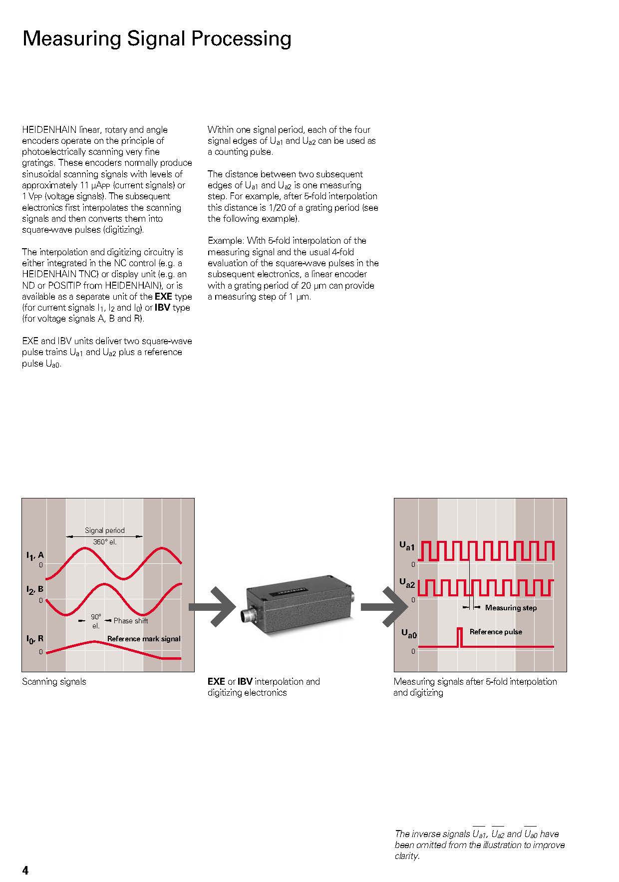
Andy unfortunately not, however I did get my mind more clear from reading this page of the manual.
So my:
a0 is reference
a1 is Phase A
a2 is Phase B
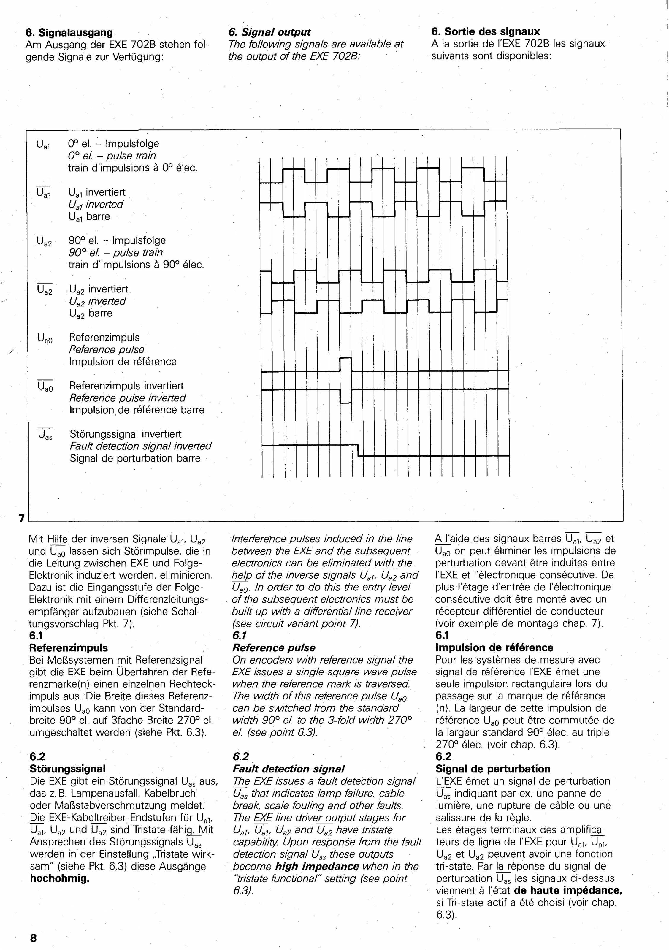
Uas is Fault monitoring
When I get back home ill re-wire and take a snapshot of the scope, where would you recommend I read to get the concepts down for using the hal scope? I messed with it yesterday but I need to get some basics down, for initial motor tuning and initial encoder testing.
So I need to wire this way?
EXE A1===> 7I77 QA0
EXE A2===> 7I77 QB0
EXE A0===> 7I77 IDX
So my:
a0 is reference
a1 is Phase A
a2 is Phase B
Uas is Fault monitoring
When I get back home ill re-wire and take a snapshot of the scope, where would you recommend I read to get the concepts down for using the hal scope? I messed with it yesterday but I need to get some basics down, for initial motor tuning and initial encoder testing.
So I need to wire this way?
EXE A1===> 7I77 QA0
EXE A2===> 7I77 QB0
EXE A0===> 7I77 IDX
Last edit: 14 Jan 2016 16:47 by cncnoob1979.
Please Log in or Create an account to join the conversation.
- cncnoob1979
-
Topic Author
- Offline
- Platinum Member
-
Less
More
- Posts: 403
- Thank you received: 75
14 Jan 2016 17:07 - 14 Jan 2016 19:44 #68394
by cncnoob1979
Replied by cncnoob1979 on topic Planning - Bridgeport Interact 1 linuxCNC Retrofit
Well now that I know what I'm looking for I found the outputs for the Exe in the manual here:
ERO 115 Encoder output Pin Layout
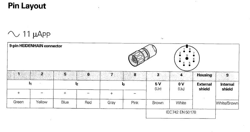
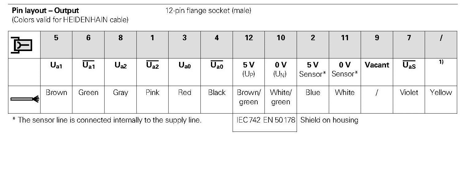
Heidenahain 12 Pin Cable Pinout
ERO 115 Encoder output Pin Layout
Heidenahain 12 Pin Cable Pinout
Last edit: 14 Jan 2016 19:44 by cncnoob1979.
Please Log in or Create an account to join the conversation.
- cncnoob1979
-
Topic Author
- Offline
- Platinum Member
-
Less
More
- Posts: 403
- Thank you received: 75
15 Jan 2016 00:08 - 15 Jan 2016 00:09 #68418
by cncnoob1979
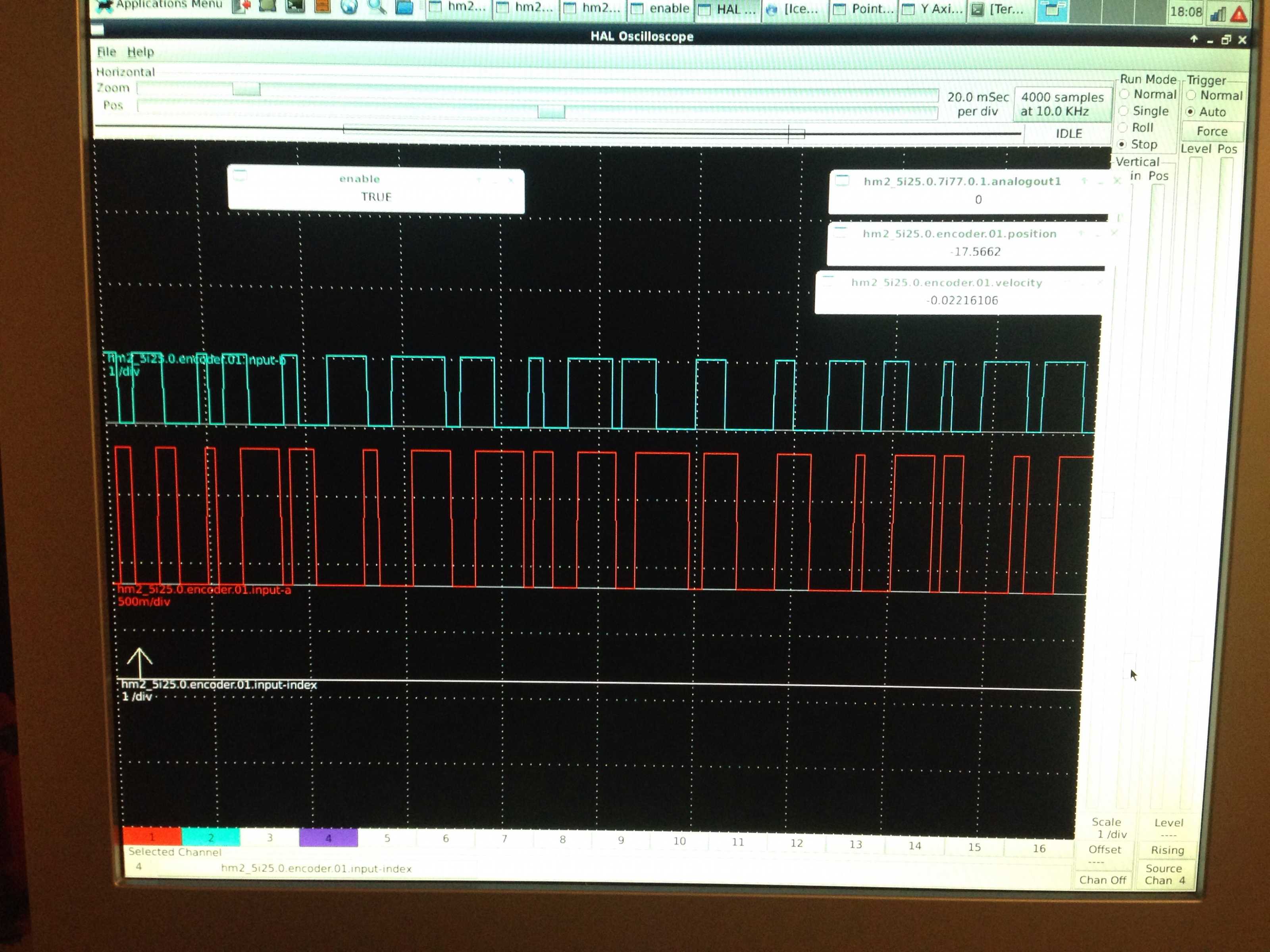
I'm not getting an index signal. Any ideas or suggestions? I'm not even sure I have things setup right!
Replied by cncnoob1979 on topic Planning - Bridgeport Interact 1 linuxCNC Retrofit
I'm not getting an index signal. Any ideas or suggestions? I'm not even sure I have things setup right!
Last edit: 15 Jan 2016 00:09 by cncnoob1979.
Please Log in or Create an account to join the conversation.
Time to create page: 0.479 seconds