Planning - Bridgeport Interact 1 linuxCNC Retrofit
- cncnoob1979
-
 Topic Author
- Offline
- Platinum Member
-

- Posts: 403
- Thank you received: 75
Bridgeport Series I Interact 1 Retrofit (CNCZONE)
Bridgeport Series 1 Interact 1 -- NOT THE MARK 2
I'm contemplating purchasing this mill with the intent of retrofitting this to LinuxCNC. Im needing help deciding the best way to accomplish this.
I'm very good with mechanics but have no experience with this type of retrofit. I'm good with basic hand tools and I know how to research for
the information necessary to retrofit this machine. However; I do not have the experience or knowledge to just "slap" it together. Any help will
be much appreciated.
My plan as of this writing:
1) purchase mesa 5i25+7i77 card for the io's and Motion card. 7I77-5I25 PLUG-N-GO KIT
2) Keep existing servo's and amps
3) Wire for 220 Single Phase ( I understand just the spindle is 3ph 220)
4) Use existing transformers or buy/build another one to supply the proper voltages.
5) VFD for the Spindle
Here is the Cabinet:

Get started making chips!
Obviously this wont be easy and I do not back down from a challenge.
The mill had a Heidenhain TCN-151 controller and was previously removed from the owner. (And the CRT)
Everything in the electrical cabinet I am told is still there.
I have read Igor's thread on his build as well as what i could find on JT's Garage.
First issue I have ran across is the Servo Amps.

I have been unable to find any information on these (Z15-1-240v) and when I do find them listed they have been
removed from previous retrofits. Is there a reason I can not use these? I was under the impression I could use
a converter card to use the +-10v that the Mesa hardware needs.
If I can not use these then what are some other "tried" and documented methods? Before you tell me to read and
"let me google that for you" I will let you know I have been researching for about a year. Yes I know I do not know the
lingo and am leaving out a lot of probably needed information. But I am learning and enjoying the experience.
I have not purchased this machine yet - Im still trying to plan. The price is right and seems to be what i would want.
A VMC is too much for me at the moment, but I would love to have one
")
This is for a Project and Hobby use - even so - its still exciting to get started. If I can come up with a proper
plan I would purchase this machine next weekend if it is still available.
The DC Servo Motors I have are these:
Would I need to install E5 Optical Encoders on the motors?

I have seen that JohnT has completed this retrofit and used the controller to convert the signals from the resolvers to something usable for the mesa hardware.
I do not have any of the original controller remaining. So my question is if I use the E5 Encoders I should be able to use my servo amps as they are?
Sorry I'm very new and trying to wrap my head around this! Break it down barney style please!
Please Log in or Create an account to join the conversation.
- andypugh
-

- Away
- Moderator
-

- Posts: 19875
- Thank you received: 4641
I have seen that JohnT has completed this retrofit and used the controller to convert the signals from the resolvers to something usable for the mesa hardware.
I do not have any of the original controller remaining. So my question is if I use the E5 Encoders I should be able to use my servo amps as they are?
Are you sure that the motors have resolvers? From the motor plate it is clear that they have tachometers.
Tachometers are used to close the velocity loop in the drives. It's actually a really simple feedback system. You apply a command voltage, the tachometer voltage is added to the command voltage, but back-to-front so that it cancels out when they are equal. Then the resulting voltage is amplified in voltage and current and sent to the motors. This is why they call them servo amps.
Resolvers and encoders are two different positional feedback systems. As someone on the IRC said a few weeks ago "Resolvers are better in every way except price". If you have resolvers, then keep them.
To control velocity servos with DC brushed drives then I would suggest something other than the normal 5i25 / 7i77 combo. I am currently building a machine using the 6i24 and the Mesa 7i49 There is a similar card with full size PCI if that is what your motherboard has. When JT converted his system there wasn't a Mesa Resolver board.
This gives you position to 12 bits of accuracy, equivalent to 4096 count encoders, but without the single-count dithering of an encoder, which makes it work rather better with a PID controller {opinion}
In fact, I took the encoder off of one of my motors to fit a resolver.
The 7i49 supplies 6 x +/-10V signals to drive your servo drives. (the extras might come in handy for rotary tables etc).
These cards are a different family to the 5i25 boards. They have 50-pin headers with 24 IO pins rather than DB25 headers with 17 IO pins, and take a slightly different family of daughter cards. There is a second class of cards that communicate via a Mesa-invented protocol called Smart-Serial, and those can connect to either class of card.
A quick summary of Mesa cards is:
(Parallel port / PCI / PCIe / SPI / Ethernet -- PC interface)
|
(DB25 / 50-pin header -- FPGA Card)
|
("Native" daughter boards - Stepgens, PWM, encoders, Resolvers, UARTS)
|
(optional smart-serial boards - Mainly GPIO, but also analogue IO, MPG etc)
For general purpose IO there are many options. I decided I wanted to run some remote IO and MPGs so went for a 7i44 8-way serial breakout on a second header, and that is connected to a 7i84 and 7i73 .
I have a header spare on the 6i24 in case my current 6 channels of resolver/analogue and 24 in / 22 out on the 7i73 and 16 in / 32 out on the 7i84 are not enough.
(in fact, if I was to max-out with smart-serial devices I could have 768 IO lines as well as the resolver interface card)
The 5i25 option can only support about half that many. But that is still plenty for most purposes.
Please Log in or Create an account to join the conversation.
- andypugh
-
- Away
- Moderator
-
- Posts: 19875
- Thank you received: 4641
Please Log in or Create an account to join the conversation.
- cncnoob1979
-
Topic Author
- Offline
- Platinum Member
-
- Posts: 403
- Thank you received: 75
Also, can I use the Bosch amps with the existing tach in the servos, as it sits? Basically just replacing the controller (TCN 151) and using the Mesa hardware you suggested.
Could you tell me if it were you what hardware from Mesa you would purchase?
I'm using the mobile page and can't reference the hardware you previously suggested. I understand the controller card/io daughter card combo - the others I believe are the gpio using smart serial interface. Do I have that correct?
3 cards basically. I like the idea of 6 axis ability. 3for xyz, one for spindle and one for a 4th (a) axis. (Future proof) also I would like to use a pendant mpg.
I'll build the computer based on my hardware that has been referenced on linuxcnc webpage.
Please Log in or Create an account to join the conversation.
- andypugh
-
- Away
- Moderator
-
- Posts: 19875
- Thank you received: 4641
Ok, so to clear my head. There are two types - resolvers and encoders. Is a tach condidered either one?
No, a tachometer is just a velocity feedback device.
With modern technology both resolvers and encoders can also give very good velocity feedback, in the digital domain, but that wasn't the case at the time these machines were built. (or, more accurately, it wasn't cost effective to do so)
If it worked before, it should all work now.Also, can I use the Bosch amps with the existing tach in the servos, as it sits? Basically just replacing the controller (TCN 151) and using the Mesa hardware you suggested.
In theory you just need to provide a new source of +/-10 V control signals. Of course your source of control signals also needs to know where the machine is, so that it can send the _right_ control signals, and that is where the position feedback from Resolvers or Encoders is needed.
If it was me, I wouldn't buy anything yet, until I had the mill home and had run some tests.Could you tell me if it were you what hardware from Mesa you would purchase?
You will definitely need a computer, so you might as well get that set up, and have a play around with the simulator configs in LinuxCNC. But I would wait for a while before committing to a specific interface or even a vendor. Good solutions are also available from Pico and from General Mechatronics.I'll build the computer based on my hardware that has been referenced on linuxcnc webpage.
Please Log in or Create an account to join the conversation.
- cncnoob1979
-
Topic Author
- Offline
- Platinum Member
-
- Posts: 403
- Thank you received: 75
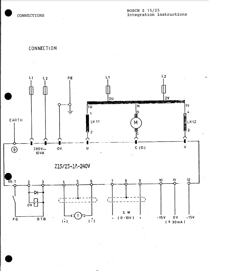
The schematic picture shown above shows one of the servo drives. Note that these servos use an analog +/- 10V velocity command for input and use a tachometer on the motor for velocity feedback. This should make the control relatively easy to setup as I only need to close the outer position loop with EMC.
For the initial setup I just used halrun with a test hal file. This way I could test to see that the motors moved according to the command signal and check the position encoder feedback. This was the first setback in the project as I found that the Heidenhain encoders produced analog sine and cosine 125 cycle/revolution output signals. So to handle the encoder output problem I took the encoder interface board from the old Heidenhain controller and mounted it on the back of the cabinet door close to the PC. The Heidenhain board then outputs 625 A quad B digital cycles per revolution giving a resolution of 2500 counts per revolution. The ball screws have a 5mm pitch and are driven by a 2:1 timing belt reduction from the motors. So 2500 counts of the encoder represents 2.5 mm of motion or .001mm per count.
Excerpt from JohnT's Build Webpage
JohnT's LinuxCNC Build Thread
Ok, So my understanding is JohnT had encoders on his servo's, when in fact he had a tach. We have/had the same controllers and from what I have read he used the same servo amps that I have So, I should be able to use Mesa hardware (6i24 and the Mesa 7i49) to interface with this setup as it is with the tach's and at least get it working as is.
So here is some of my confusion with the prior conversations.
So If I interface with the servo amp using +-10v command signals and close the loop with the tach then i should be able to use all existing hardware_Provided I can find some information on my servo amps for wiring purposes.
A user posted this to CNCZone: Shows the pins for the command voltage, assuming its +-10V. This is the schematic for a Interact 1 Mark2

Also I have installed the latest live cd of LinuxCNC and played with the simulator somewhat. Getting my interface working may prove difficult but I dont have to purchase anything to make that work - just a butt load of research and debugging! (I have played with linux since 2005 and somewhat familiar with the file layout commands ect.., but only for fun!)
Please Log in or Create an account to join the conversation.
- andypugh
-
- Away
- Moderator
-
- Posts: 19875
- Thank you received: 4641
This was the first setback in the project as I found that the Heidenhain encoders produced analog sine and cosine 125 cycle/revolution output signals.
Ok, So my understanding is JohnT had encoders on his servo's, when in fact he had a tach.
Actually, he had a tachometer and a sinusoidal encoder.
I haven't mentioned sinusoidal encoders so far, something of an omission.
These are something a hybrid between an encoder and a resolver. They have an output a lot like a resolver, two sine waves 90 degrees out of phase. But they are created by optical devices, and whereas a resolver will have 1 or 2 cycles per motor revolution, the sinusoidal encoders have a few hundred. With both a sinusoidal encoder and a resolver the interface electronics takes the arctan of the ratio of the two signals to get a position.
So, you need to first decide if the motor feedback is quadrature encoder, sinusoidal encoder, or resolver. The good news is that you can use any of them with LinuxCNC. (and a few more options too)
So If I interface with the servo amp using +-10v command signals and close the loop with the tach then i should be able to use all existing hardware_Provided I can find some information on my servo amps for wiring purposes.
You can test the amps with a a low-voltage battery, but the machine will still move at 15% of max speed with a 1.5V battery.
Please Log in or Create an account to join the conversation.
- cncnoob1979
-
Topic Author
- Offline
- Platinum Member
-
- Posts: 403
- Thank you received: 75
I found literature for the Servo Amp z15-1A-240 V / z25-1A-240 V. Was buried in another thread, cant remember where I found it.
Now I need to find out about the Servo's. An encoder was an option for this install, and more then likely - was used.
If this is the case and I have a sinusoidal encoder, will I need to change my hardware? John used the controller board for his. I will not have that option.
Please Log in or Create an account to join the conversation.
- andypugh
-
- Away
- Moderator
-
- Posts: 19875
- Thank you received: 4641
It looks like the amps take single-phase input. That's a surprise, but rather convenient. It means you just need a transformer.I found literature for the Servo Amp z15-1A-240 V / z25-1A-240 V. Was buried in another thread, cant remember where I found it.
Now I need to find out about the Servo's. An encoder was an option for this install, and more then likely - was used.
If this is the case and I have a sinusoidal encoder, will I need to change my hardware? John used the controller board for his. I will not have that option.
The two main options for sinusoidal encoders are Heidenhain EXE boxes:
www.ebay.com/itm/181900885922
Or the development board from ICHaus.
www.ichaus.de/product/iC-MG
Despite what I have said earlier, I would be tempted to grab those EXE boxes just in case that that price, then maybe put them back on eBay if they are not suitable.
Please Log in or Create an account to join the conversation.
- cncnoob1979
-
Topic Author
- Offline
- Platinum Member
-
- Posts: 403
- Thank you received: 75
Good deal! Just bought all 4 he had available on eBay (exe boxes) - total 132 shipped. If it turns out I don't need them am pretty confident I can get my money plus some. I got the fourth so I can sell it and hopefully recoup my initial purchase price. Now I have to read up on how to use these.. any lead where to get the best information?
Please Log in or Create an account to join the conversation.