Planning - Bridgeport Interact 1 linuxCNC Retrofit
- cncnoob1979
-
 Topic Author
- Offline
- Platinum Member
-

- Posts: 403
- Thank you received: 75


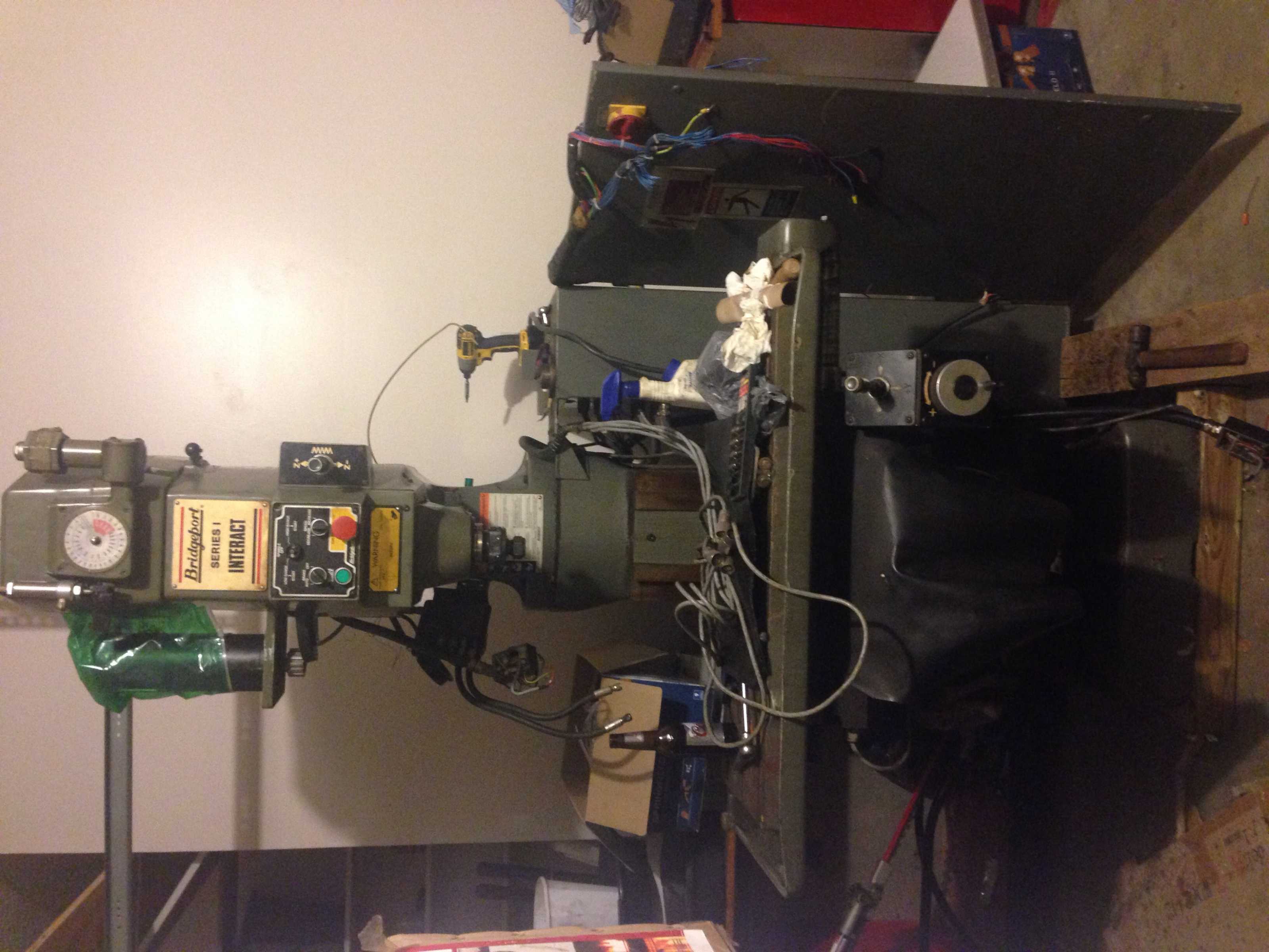
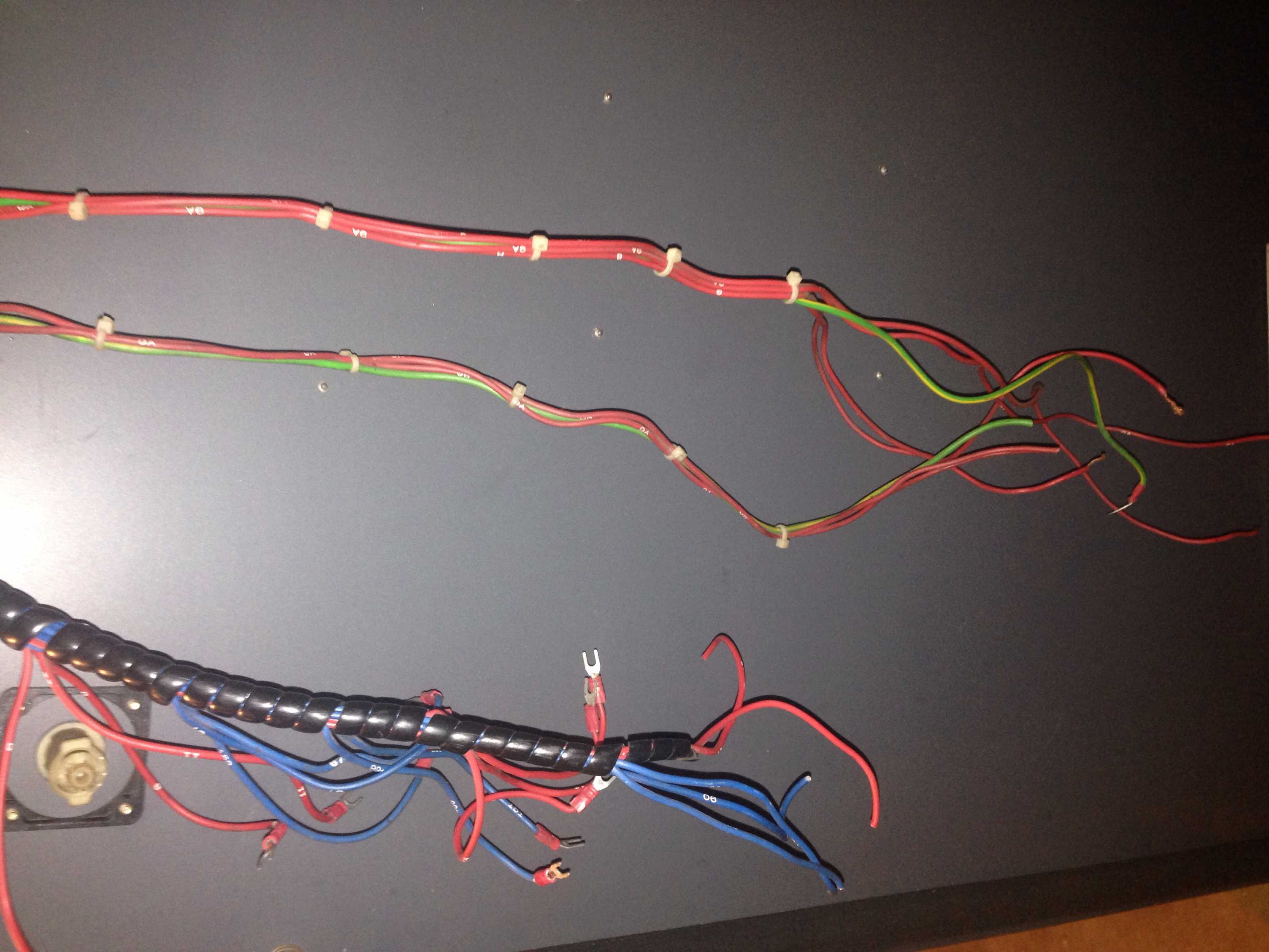
And it's in the garage and head is off! Disassembled as one unit. The way the unit separated I found that it was not necessary to disassemble the wiring harness from the control panels, because the centering disc kept the machine from shearing the wiring cables.
Please Log in or Create an account to join the conversation.
- andypugh
-

- Offline
- Moderator
-

- Posts: 19875
- Thank you received: 4642
Please Log in or Create an account to join the conversation.
- cncnoob1979
-
Topic Author
- Offline
- Platinum Member
-
- Posts: 403
- Thank you received: 75
Yes I used a 1 1/2 ton engine crane and 10k straps to remove the components.
I used a 6k pallet Jack and a 8k cable hoist to pull it into my garage. I bolted a 1/2 inch concrete wedge anchor into the concrete floor for a pulling point. I had to use the hoist (in the very back of my garage, centered in my garage) due to the fact I have a about a 4 foot 8degree grade into my garage from the driveway. So pushing it was not an option.

Here is how I attached my sling to the garage floor. I drilled a 1/2 hole into the metal bracket.


This mill was from a Tech School in Tennessee. Sat in a shop for 6 years before he got rid of it. Looking at the saddle i would say it should be a tight machine.
Please Log in or Create an account to join the conversation.
- andypugh
-
- Offline
- Moderator
-
- Posts: 19875
- Thank you received: 4642
This mill was from a Tech School in Tennessee. Sat in a shop for 6 years before he got rid of it. Looking at the saddle i would say it should be a tight machine.
Looking at the scrape marks it looks like it might never have been used...
Please Log in or Create an account to join the conversation.
- cncnoob1979
-
Topic Author
- Offline
- Platinum Member
-
- Posts: 403
- Thank you received: 75
I'm contemplating acquiring a 3phase converter for this machine, then purchase a VFD for it later.
Would I damage my machine by hooking it up to single phased 220v power? Something to disconnect or remove prior to? Or would it be best to have a 3ph converter first?
Thoughts? Comments? Suggestions?
Please Log in or Create an account to join the conversation.
- cncnoob1979
-
Topic Author
- Offline
- Platinum Member
-
- Posts: 403
- Thank you received: 75
Please Log in or Create an account to join the conversation.
- andypugh
-
- Offline
- Moderator
-
- Posts: 19875
- Thank you received: 4642
Please Log in or Create an account to join the conversation.
- cncnoob1979
-
Topic Author
- Offline
- Platinum Member
-
- Posts: 403
- Thank you received: 75
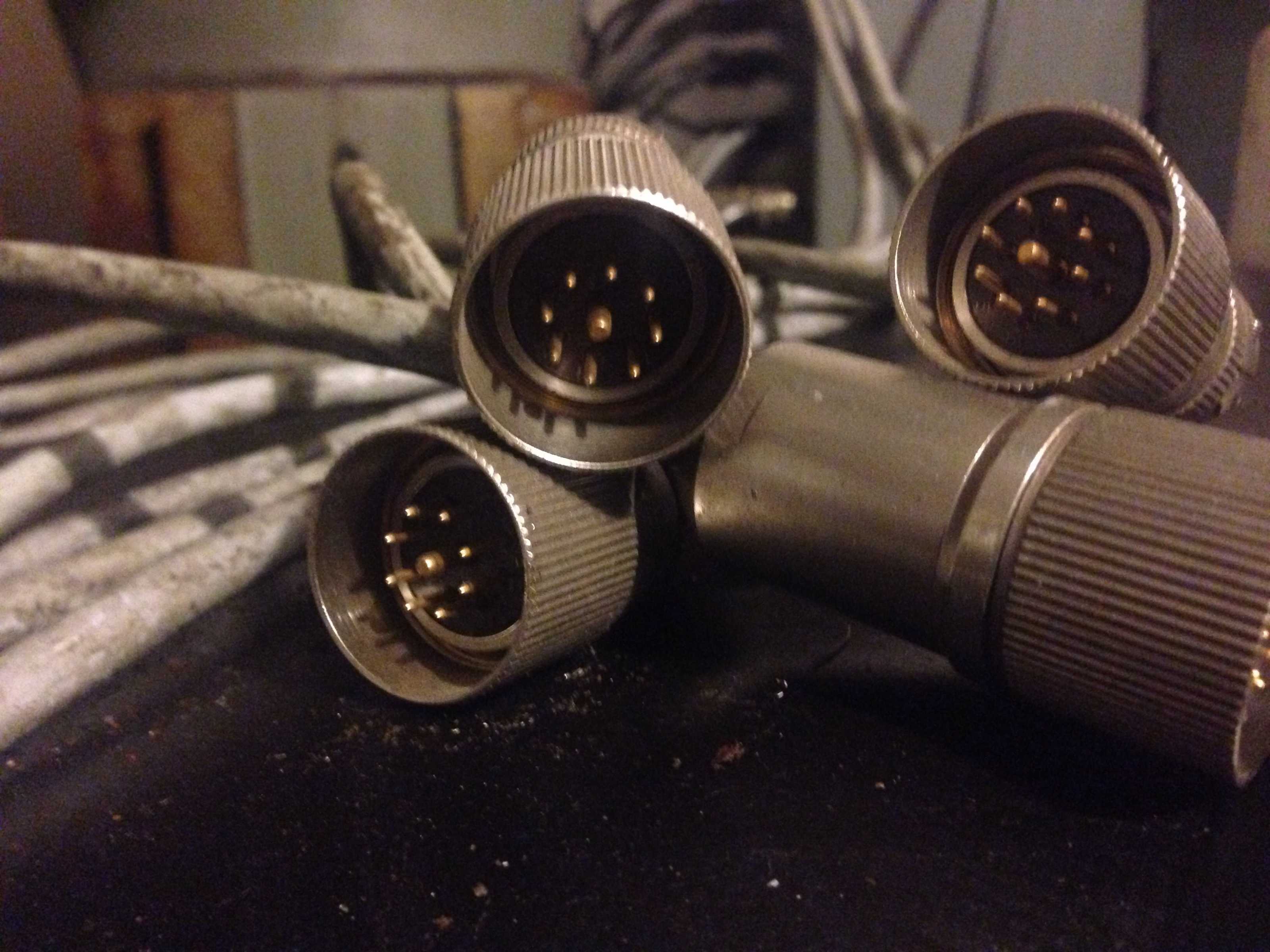
Andy, the encoders terminate in 9 pin male plugs. I'm considering the exe boxes at the moment.
Most of my connections to the TCN-151 controller was cut. Not much of a bad deal. Also one of my encoder cables were cut. I can just shorten and install to the servo, I have plenty of slack.
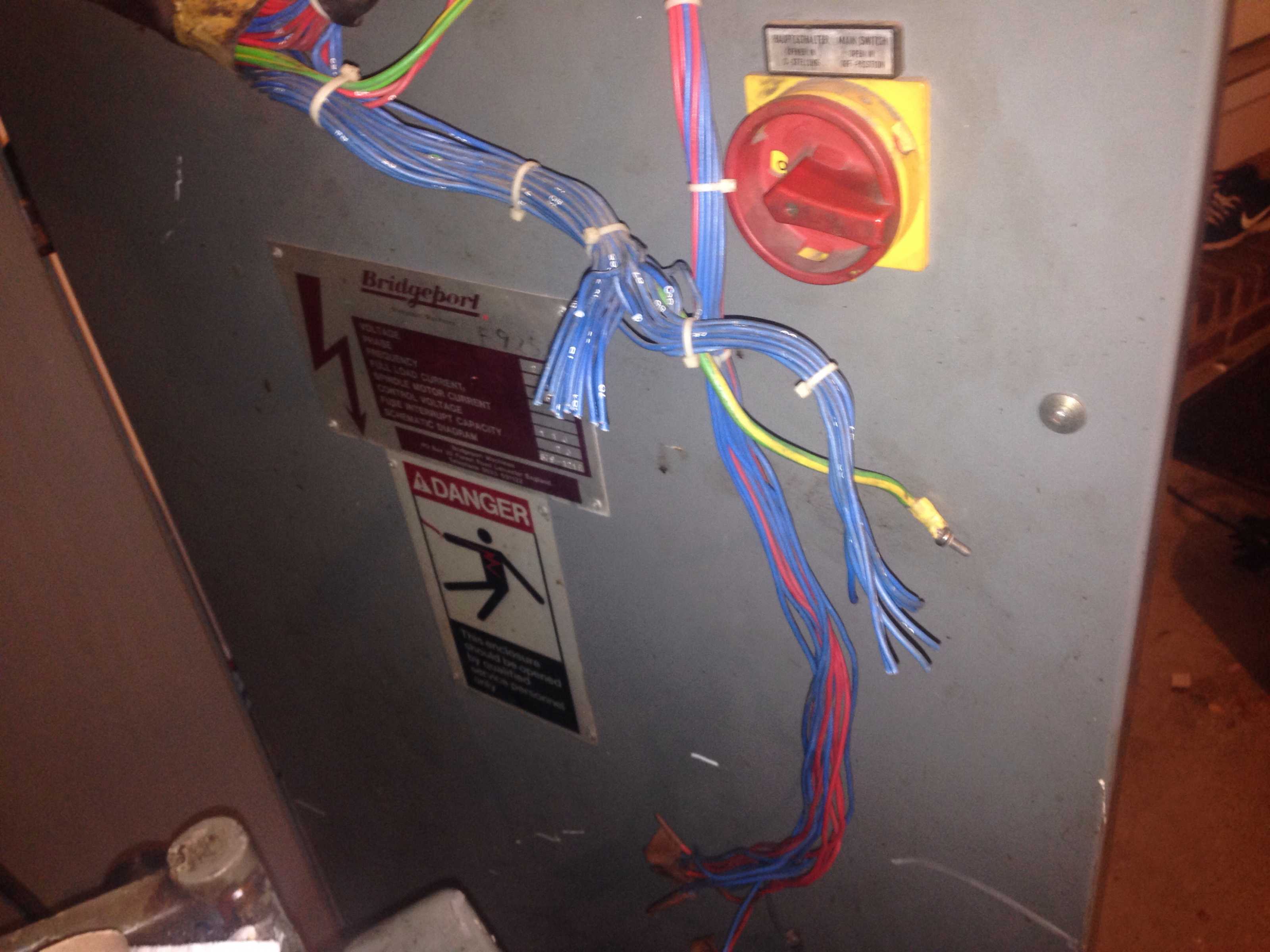
The T2 transformer is an auto-transformer from my understanding. In the wiring schematic it shows it as using 103 and 104 as a power source. L1,L2 So I believe this is a step up transformer because the required voltage going to my servo amps require 380v input. Is this accurate? Or am I misreading the schematic?
Please Log in or Create an account to join the conversation.
- andypugh
-
- Offline
- Moderator
-
- Posts: 19875
- Thank you received: 4642
The encoders look like they will plug straight in to those EXE boxes that you bought and then cancelled.Andy, the encoders terminate in 9 pin female plugs. I'm considering the exe boxes at the moment.
So that just leaves the puzzle of finding connectors for the outputs, which Mouser seem to sell at a reasonable price.
The T2 transformer is an auto-transformer from my understanding. In the wiring schematic it shows it as using 103 and 104 as a power source. L1,L2 So I believe this is a step up transformer because the required voltage going to my servo amps require 380v input. Is this accurate? Or am I misreading the schematic?
If it was only L1 and L2 then I would say that you only need to re-arrange the input terminals to suit your mains voltage.
However, I am rather puzzled by the function of the UV inputs which seem like they might be + / - 180 V relative to the 0V line.
Maybe it would be wise to disconnect the outputs, re-arrange the inputs and check output voltages.
Please Log in or Create an account to join the conversation.
- cncnoob1979
-
Topic Author
- Offline
- Platinum Member
-
- Posts: 403
- Thank you received: 75
Well good news. The autotransformer does step up voltage.
In accordance with the schematic I checked 0v line and my 380v line and received around 350v. My L2 (#112) is connected to 210v on the T2 transformer. (Was wired previously for 210 3ph).(I need to move it to the 220) I had to actuate 5FC relay manually to get the power to T2. I haven't figured out what signal to actuate it yet.
Now the bad news. I blew a resistor in my control cabinet upon first actuation of 5FC. (Scared the **** out of me!)
Attached is the resistor I'm currently trying to figure out what it goes to. I think power is heading toward my z axis limit switch wiring. (I had one disconnected and grounded) I think it was a 3R3 prior to me destroying it. But that is from memory.
I'm a child playing pilot in an Airbus here!
Alright. Traced it down to R7, #169 and #7. Guess I took out the z axis power resistor. Now to find a replacement. I think I found the short. I'm at fault. I had the wires hanging from the encoder box but failed to ensure one wasn't grounded. :doh:
Maybe someone should take this machine from me before I destroy it!
")

So now the question: where to get a replacement and when the drive amps are powered are the servos immediately powered? I'm pretty sure I tested that. But just incase it should not have happened.

Would this be a suitable replacement?
3.3 ohms/10W
Please Log in or Create an account to join the conversation.