- Posts: 403
- Thank you received: 75



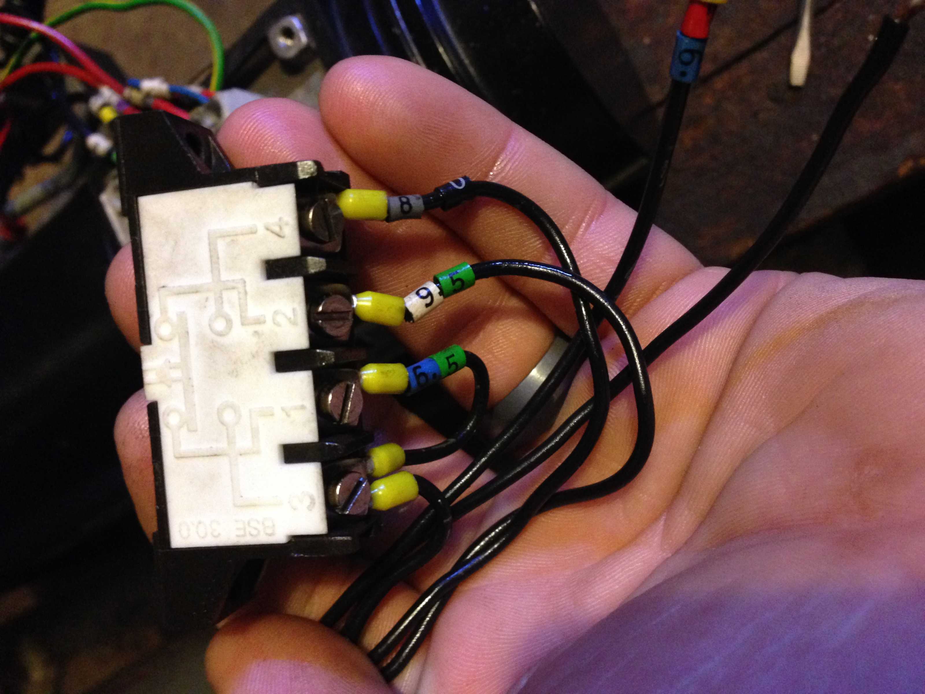
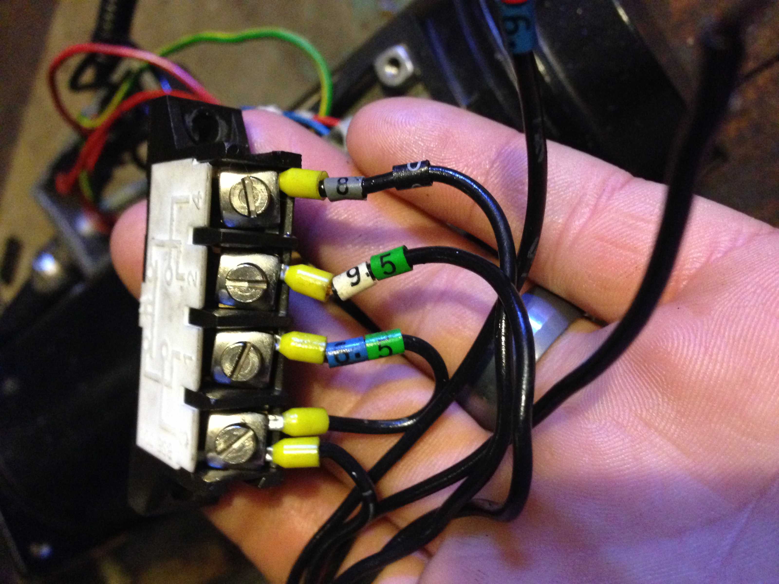
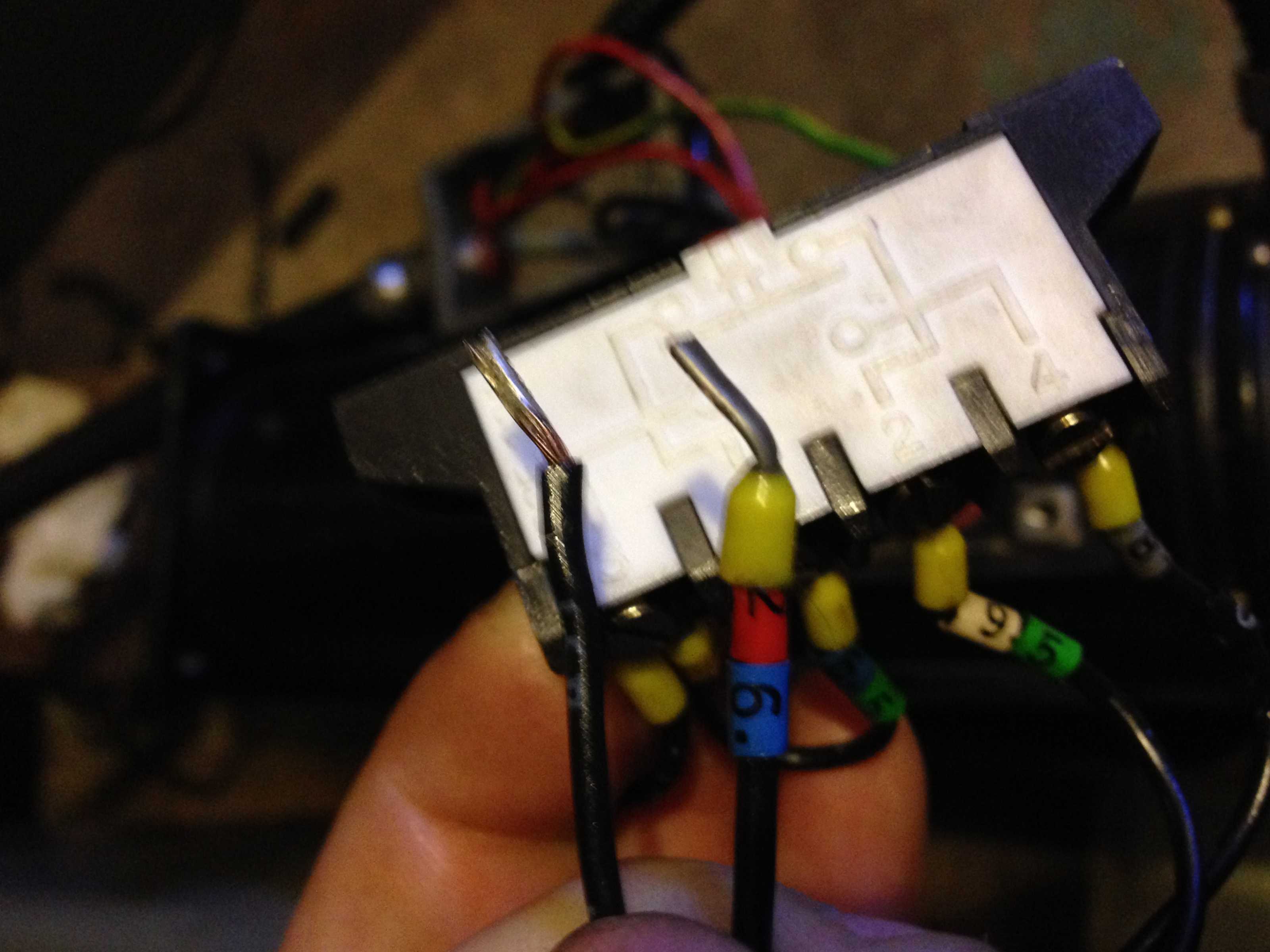
Please Log in or Create an account to join the conversation.
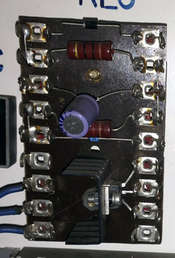


Please Log in or Create an account to join the conversation.
cncnoob1979 wrote: I removed the blown resistor located on the 2nd leg from the top. Anyone can you tell what size it is? Looks gold, black, black, brown. I'll check the tables for the 4 banded resistors and see if it makes sense. [Edit: its a 10 Ohms 5%, Watt's unknown] suggestions?]
Please Log in or Create an account to join the conversation.

Please Log in or Create an account to join the conversation.
Please Log in or Create an account to join the conversation.
Please Log in or Create an account to join the conversation.

