PID issues or calibration help
- Todd Zuercher
-

- Away
- Platinum Member
-

- Posts: 4757
- Thank you received: 1459
Also you must forgive me but if John's tutorial is right he states: FF1 - Should be 10/Velocity@10V (velocity in machine units per second). We both agree my velocity is about 1.6315 ipm ...if that's the case then John's equation, as he has it written is (10 / 1.6315) which equals 6.129 in my case. But what you said is John's equation is backwards and should be: FF1 - Should be Velocity@10V (velocity in machine units per second) / 10. Which in my case is 1.6315 / 10 ( .163 ). So hopefully you guys can see what I mean when I state that there are some glaring problems we need to work together to fix if people are to follow these tutorials. I am happy to help fix them if you guys will just help me figure things out.
No, I am probably, almost certainly, wrong, (been running a fever the last couple of days and I was probably not thinking very clearly when I wrote that.)
Please Log in or Create an account to join the conversation.
- PCW
-

- Offline
- Moderator
-

- Posts: 17971
- Thank you received: 5270
This has the nice side effect of making the PID terms commensurate between different machines (for example inch and mm configurations for the same hardware will now use the same PID terms)
Please Log in or Create an account to join the conversation.
- hatch789
-
 Topic Author
- Offline
- Premium Member
-

- Posts: 143
- Thank you received: 0
So to your suggestion PCW, are you saying to set my tree.ini file to have this setting? Since it ran at 98 ipm at 10v. I will verify that it's truly giving only 10v to achieve this high speed. Is there an easy way for me to see my output voltage by just looking at the proper pin?
RESOLVER_SCALE = -.2
OUTPUT_SCALE = 98.0
MAX_OUTPUT = 10.0
MIN_LIMIT = -0.001
MAX_LIMIT = 30.8
If that's all that's to it, I can do that tonight no problem. So are the negative FF1 tests that I did absolutely crazy or have you seen that happen before where negative FF1 actually helps reduce errors?
Please Log in or Create an account to join the conversation.
- PCW
-
- Offline
- Moderator
-
- Posts: 17971
- Thank you received: 5270
So something very basic is wrong if 0 or negative FF1 values
give minimum errors
All LinuxCNC velocity units are per second so the output scale would be 1.63
Please Log in or Create an account to join the conversation.
- Todd Zuercher
-
- Away
- Platinum Member
-
- Posts: 4757
- Thank you received: 1459
it would be 98/60 = 1.6333.
Also does the motor turn in the positive or negative direction when a positive voltage is applied?
Please Log in or Create an account to join the conversation.
- hatch789
-
Topic Author
- Offline
- Premium Member
-
- Posts: 143
- Thank you received: 0
I will check the direction the motor runs tonight. I'm assuming I can just use the HAL Monitor to see the voltage that I'm feeding my amp on the signal wire? I will check it with a volt meter as well but HAL Monitor should show a voltage right?
Please Log in or Create an account to join the conversation.
- OT-CNC
- Offline
- Platinum Member
-
- Posts: 617
- Thank you received: 75
I have replaced my entire Westamp servo drive unit with a new one that does not squeal anymore and I have tuned that Westamp drive according to the PDF file you saw me attach several posts back. To anyone who is not an expert, watching my machine it seems to be working perfectly and move accurately. Fast, slow circles, repetitive operations. You name it, the machine seems to be fine.
Not to go off track here but what drives did you replace the old ones with? Is it the 651 shown on the PDF? I have an older machine that squeals. May need to replace my drives sometime. How did you end up tuning the drives before connecting to linuxcnc? Did you use a scope on the tach?
I'm following this as I probably will run into trouble once I mess with replacing the old drives.
Please Log in or Create an account to join the conversation.
- hatch789
-
Topic Author
- Offline
- Premium Member
-
- Posts: 143
- Thank you received: 0
I have replaced my entire Westamp servo drive unit with a new one that does not squeal anymore and I have tuned that Westamp drive according to the PDF file you saw me attach several posts back. To anyone who is not an expert, watching my machine it seems to be working perfectly and move accurately. Fast, slow circles, repetitive operations. You name it, the machine seems to be fine.
Not to go off track here but what drives did you replace the old ones with? Is it the 651 shown on the PDF? I have an older machine that squeals. May need to replace my drives sometime. How did you end up tuning the drives before connecting to linuxcnc? Did you use a scope on the tach?
I'm following this as I probably will run into trouble once I mess with replacing the old drives.
Basically I swapped the entire westamp module it's the size of about half a car battery. 2 boards and a power supply with a huge coke-can capacitor. If you look in my oupower.com website you'll see pics of the boards I swapped out.
I was lucky enough to get a slightly newer driver board that matched up (same model #) as my old one, just newer revision. So my tuning was minimal. I uploaded a PDF to this thread earlier, print that out and it gives you the crap in the middle where you set your drives to x turns from the end. There were (in my case) 6 high resolution POTS. The old board had 18 turns per POT, the new board has 28 turns per POT so I had to adjust to the difference and get things pretty "good" ...really the TC and the TACH are the only 2 true adjustments for how the servo runs. The current limit just affects speed and the balance is used after to fix drift. SIG and AUX are for input, I only use AUX and nothing is on SIG. I think that's it.
I can help you more if you have questions there. And I can take more pics if it'll help you.
Please Log in or Create an account to join the conversation.
- hatch789
-
Topic Author
- Offline
- Premium Member
-
- Posts: 143
- Thank you received: 0
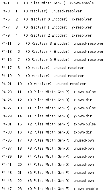
Look at GPIO 0 and also 23? Why would these both be Gen-E with x-pwm-enable? Maybe it's right but I want you to verify.
Also, if I want to watch my voltage for X and Y which pins would I watch?
Attachments:
Please Log in or Create an account to join the conversation.
- OT-CNC
- Offline
- Platinum Member
-
- Posts: 617
- Thank you received: 75
Please Log in or Create an account to join the conversation.