7i96 step + or -, + other question
- Leon82
- Offline
- Platinum Member
-

Less
More
- Posts: 592
- Thank you received: 79
28 Nov 2019 17:01 #151437
by Leon82
Replied by Leon82 on topic 7i96 step + or -, + other question
I found another and a post where the guy originally tried the 55 timer and used an Arduino board.
www.hobby-machinist.com/threads/another-...n.53938/#post-454352
www.hobby-machinist.com/threads/another-...n.53938/#post-454352
Attachments:
Please Log in or Create an account to join the conversation.
- PCW
-

- Away
- Moderator
-

Less
More
- Posts: 17996
- Thank you received: 5282
28 Nov 2019 17:31 #151445
by PCW
Replied by PCW on topic 7i96 step + or -, + other question
If the PWM is that slow, you could probably use one of the 7I96s isolated outputs
and software PWM in hal to avoid connecting the drive ground to the 7I96 ground (for EMI reasons)
and software PWM in hal to avoid connecting the drive ground to the 7I96 ground (for EMI reasons)
The following user(s) said Thank You: Leon82
Please Log in or Create an account to join the conversation.
- Leon82
- Offline
- Platinum Member
-
Less
More
- Posts: 592
- Thank you received: 79
28 Nov 2019 18:06 #151446
by Leon82
Thanks.
I'll search for some examples
Replied by Leon82 on topic 7i96 step + or -, + other question
If the PWM is that slow, you could probably use one of the 7I96s isolated outputs
and software PWM in hal to avoid connecting the drive ground to the 7I96 ground (for EMI reasons)
Thanks.
I'll search for some examples
Please Log in or Create an account to join the conversation.
- Leon82
- Offline
- Platinum Member
-
Less
More
- Posts: 592
- Thank you received: 79
30 Nov 2019 05:42 - 30 Nov 2019 13:47 #151555
by Leon82
Replied by Leon82 on topic 7i96 step + or -, + other question
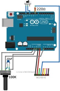
What's the best way to invert an axis with the 7i96? In the Hal or switch the motor winding order?
I'm planning on hooking up my limit/home switches like this picture.
I tried adding a -not at the end of the hall file to invert one of the limits and it doesn't do anything. Do I have to adjust it somewhere else?
I'm planning on hooking up my limit/home switches like this picture.
I tried adding a -not at the end of the hall file to invert one of the limits and it doesn't do anything. Do I have to adjust it somewhere else?
Attachments:
Last edit: 30 Nov 2019 13:47 by Leon82.
Please Log in or Create an account to join the conversation.
- rodw
-

- Offline
- Platinum Member
-
Less
More
- Posts: 12049
- Thank you received: 4114
30 Nov 2019 22:06 #151610
by rodw
Replied by rodw on topic 7i96 step + or -, + other question
Careful. I have heard switching DC power to the drives is surefire way to blow up your drives. You are far better off dropping mains power to the motor power supply on estop but that would require another power supply.
Another option for etop would be to configure an output to the estop out signal and use it to disable the drives via the enable inputs. You can steal some power from the 5V stepgens and switch it on the output relay.
I never got enough torque at 24 volts in my initial playing with stepper drives. I'm not sure what is the maximum your drives can handle but I used 48v on both NEMA 23 and NEMA 17's. You might be limited to 36 volts.
Also do not daisy chain power to your drives, be sure you wire in a star configuration back to the power supply for each drive.
The following user(s) said Thank You: Leon82
Please Log in or Create an account to join the conversation.
- Leon82
- Offline
- Platinum Member
-
Less
More
- Posts: 592
- Thank you received: 79
30 Nov 2019 22:21 #151613
by Leon82
I'm only using that picture for the input wiring which worked well.
I have mine at 35 volts for the steppers for now the supplies go to 60 but probably won't go much over 48 with a load.
I watched the video and understand what I need to do for software estop.
XYZ are gecko drives so can wire the disable terminal thru a relay on the other side of the estop button if I wanted. The rotary is a kl 5056 so that one would be different.
Replied by Leon82 on topic 7i96 step + or -, + other question
Careful. I have heard switching DC power to the drives is surefire way to blow up your drives. You are far better off dropping mains power to the motor power supply on estop but that would require another power supply.
Another option for etop would be to configure an output to the estop out signal and use it to disable the drives via the enable inputs. You can steal some power from the 5V stepgens and switch it on the output relay.
I never got enough torque at 24 volts in my initial playing with stepper drives. I'm not sure what is the maximum your drives can handle but I used 48v on both NEMA 23 and NEMA 17's. You might be limited to 36 volts.
Also do not daisy chain power to your drives, be sure you wire in a star configuration back to the power supply for each drive.
I'm only using that picture for the input wiring which worked well.
I have mine at 35 volts for the steppers for now the supplies go to 60 but probably won't go much over 48 with a load.
I watched the video and understand what I need to do for software estop.
XYZ are gecko drives so can wire the disable terminal thru a relay on the other side of the estop button if I wanted. The rotary is a kl 5056 so that one would be different.
Please Log in or Create an account to join the conversation.
- tommylight
-

- Offline
- Moderator
-
Less
More
- Posts: 21763
- Thank you received: 7438
30 Nov 2019 22:23 #151615
by tommylight
Replied by tommylight on topic 7i96 step + or -, + other question
A very good advice from Rod, switching DC side is never a good idea in this case.Careful. I have heard switching DC power to the drives is surefire way to blow up your drives. You are far better off dropping mains power to the motor power supply on estop but that would require another power supply.
The following user(s) said Thank You: Leon82
Please Log in or Create an account to join the conversation.
- Leon82
- Offline
- Platinum Member
-
Less
More
- Posts: 592
- Thank you received: 79
30 Nov 2019 22:25 #151617
by Leon82
Thanks, yes I have a direct run from the supply terminal to the drive.
Replied by Leon82 on topic 7i96 step + or -, + other question
A very good advice from Rod, switching DC side is never a good idea in this case.Careful. I have heard switching DC power to the drives is surefire way to blow up your drives. You are far better off dropping mains power to the motor power supply on estop but that would require another power supply.
Thanks, yes I have a direct run from the supply terminal to the drive.
Please Log in or Create an account to join the conversation.
- Leon82
- Offline
- Platinum Member
-
Less
More
- Posts: 592
- Thank you received: 79
01 Dec 2019 03:20 #151628
by Leon82
Replied by Leon82 on topic 7i96 step + or -, + other question
I got it to work like in his video.
I would think you could use a pin and relay linked to the power button so when you release estop and press power the power supply for the drives will turn on and hitting estop would kill the power to the drives.
I would think you could use a pin and relay linked to the power button so when you release estop and press power the power supply for the drives will turn on and hitting estop would kill the power to the drives.
Please Log in or Create an account to join the conversation.
- Leon82
- Offline
- Platinum Member
-
Less
More
- Posts: 592
- Thank you received: 79
01 Dec 2019 20:42 #151692
by Leon82
Replied by Leon82 on topic 7i96 step + or -, + other question
im trying to use an output for spindle on but thru the 7i96 tool i get this i set one for cw and one for on
net spindle-cw motion.spindle-forward => hm2_7i96.0.ssr.00.out-01
net spindle-on motion.spindle-on => hm2_7i96.0.ssr.00.out-02
both say pin not found in halcmd, cnc wont load. it errors out with the same error
playing around i entered this and the signal showed up of the hal meter
net spindle-fwd => hm2_7i96.0.ssr.00.out-01
but stays false
Please Log in or Create an account to join the conversation.
Time to create page: 0.156 seconds