Search Results (Searched for: stepper spindle)
- Will_cnc
- Will_cnc
25 Oct 2025 12:24
Stepper online A6 Servo motor as Spindle motor was created by Will_cnc
Stepper online A6 Servo motor as Spindle motor
Category: General LinuxCNC Questions
I have a Stepperonline 1000W servo motor with an EtherCAT servo drive, which I intend to use as a temporary spindle motor until I can upgrade to a higher-power unit.
Currently, I have three axes configured to work with Leadshine servo drives via EtherCAT.How can I configure this servo motor to function as a spindle motor?
Specifically, what needs to be added or modified in the following configuration files:I’ve tried setting it up based on information from other forum posts, but I haven’t had much success so far.
Currently, I have three axes configured to work with Leadshine servo drives via EtherCAT.How can I configure this servo motor to function as a spindle motor?
Specifically, what needs to be added or modified in the following configuration files:
.INI .HAL. .XML- distro88
- distro88
23 Oct 2025 18:32 - 23 Oct 2025 18:33
torch moving UP when it should be moving DOWN was created by distro88
torch moving UP when it should be moving DOWN
Category: Plasmac
Hello everyone,
I’m having a strange issue with QtPlasmaC (version 2.9.238 / LinuxCNC 2.9.2) and my PROMA THC 150 connected to a Mesa 7i92 card.
Everything on my machine moves correctly — all axes jog fine, torch on/off works, ARC OK is detected correctly, and the THC UP and DOWN inputs show properly in HAL meter.
However, during cutting:
When the THC UP signal is active, the torch moves up
When the THC DOWN signal is active, the torch moves up instead of down
Both UP and DOWN signals appear normally in HAL meter as true/false.
Here’s my setup:
Controller: Mesa 7i92 + db25 bib (raw pins)
Plasma: PROMA THC 150
QtPlasmaC version: 2.9.238 (LinuxCNC 2.9.2)
QtPlasmaC Mode: External THC (UP/DOWN/ARC OK)
THC wiring: optocoupled to Mesa inputs
Firmware: 7i92_7i76x1D.
I’ll attach my .hal and .ini files below.
.hal[/code]
I’m having a strange issue with QtPlasmaC (version 2.9.238 / LinuxCNC 2.9.2) and my PROMA THC 150 connected to a Mesa 7i92 card.
Everything on my machine moves correctly — all axes jog fine, torch on/off works, ARC OK is detected correctly, and the THC UP and DOWN inputs show properly in HAL meter.
However, during cutting:
When the THC UP signal is active, the torch moves up
When the THC DOWN signal is active, the torch moves up instead of down
Both UP and DOWN signals appear normally in HAL meter as true/false.
Here’s my setup:
Controller: Mesa 7i92 + db25 bib (raw pins)
Plasma: PROMA THC 150
QtPlasmaC version: 2.9.238 (LinuxCNC 2.9.2)
QtPlasmaC Mode: External THC (UP/DOWN/ARC OK)
THC wiring: optocoupled to Mesa inputs
Firmware: 7i92_7i76x1D.
I’ll attach my .hal and .ini files below.
.hal
# Generated by PNCconf at Wed Oct 22 23:20:44 2025
# Using LinuxCNC version:  Master (2.9)
# If you make changes to this file, they will be
# overwritten when you run PNCconf again

loadrt [KINS]KINEMATICS
loadrt [EMCMOT]EMCMOT servo_period_nsec=[EMCMOT]SERVO_PERIOD num_joints=[KINS]JOINTS num_spindles=[TRAJ]SPINDLES
loadrt hostmot2
loadrt hm2_eth board_ip="10.10.10.10" config="num_encoders=1 num_pwmgens=0 num_stepgens=5 sserial_port_0=00xxxxxx"
setp    hm2_7i92.0.watchdog.timeout_ns 5000000
loadrt pid names=pid.x,pid.y,pid.y2,pid.z,pid.s
loadrt plasmac

addf hm2_7i92.0.read          servo-thread
addf motion-command-handler   servo-thread
addf motion-controller        servo-thread
addf pid.x.do-pid-calcs       servo-thread
addf pid.y.do-pid-calcs       servo-thread
addf pid.y2.do-pid-calcs       servo-thread
addf pid.z.do-pid-calcs       servo-thread
addf pid.s.do-pid-calcs       servo-thread
addf plasmac                  servo-thread
addf hm2_7i92.0.write         servo-thread
setp hm2_7i92.0.dpll.01.timer-us -50
setp hm2_7i92.0.stepgen.timer-number 1

# ---PLASMA INPUT DEBOUNCE---
#values for these are in custom.hal
loadrt dbounce names=db_breakaway,db_float,db_ohmic,db_arc-ok
addf db_float     servo-thread
addf db_ohmic     servo-thread
addf db_breakaway servo-thread
addf db_arc-ok    servo-thread

# ---JOINT ASSOCIATED WITH THE Z AXIS---
net plasmac:axis-position joint.3.pos-fb => plasmac.axis-z-position

# ---PLASMA INPUTS---
# ---all modes---
net plasmac:float-switch     => db_float.in
net plasmac:breakaway        => db_breakaway.in
net plasmac:ohmic-probe      => db_ohmic.in
net plasmac:ohmic-sense-in   => plasmac.ohmic-sense-in
# ---modes 0 & 1
net plasmac:arc-voltage-in   => plasmac.arc-voltage-in
# ---modes 1 & 2
net plasmac:arc-ok-in        => db_arc-ok.in
# ---mode 2
net plasmac:move-up          <= plasmac.move-up
net plasmac:move-down        <= plasmac.move-down

# ---PLASMA OUTPUTS---
# ---all modes---
net plasmac:ohmic-enable     <= plasmac.ohmic-enable
net plasmac:scribe-arm       <= plasmac.scribe-arm
net plasmac:scribe-on        <= plasmac.scribe-on

# external output signals

# --- PLASMAC:TORCH-ON ---
setp hm2_7i92.0.gpio.030.is_output true
net plasmac:torch-on  =>     hm2_7i92.0.gpio.030.out
setp hm2_7i92.0.gpio.030.invert_output true

# --- PLASMAC:LASER-ON ---
setp hm2_7i92.0.gpio.031.is_output true
net plasmac:laser-on  =>     hm2_7i92.0.gpio.031.out

# --- DOUT-00 ---
setp hm2_7i92.0.gpio.032.is_output true
net dout-00  =>     hm2_7i92.0.gpio.032.out

# --- DOUT-01 ---
setp hm2_7i92.0.gpio.033.is_output true
#qtplasmac uses digital output dout-01:
#net dout-01  =>     hm2_7i92.0.gpio.033.out


# external input signals

# --- MIN-HOME-X ---
net min-home-x     <=  hm2_7i92.0.gpio.018.in

# --- MIN-HOME-Y ---
net min-home-y     <=  hm2_7i92.0.gpio.019.in

# --- MIN-HOME-Y2 ---
net min-home-y2     <=  hm2_7i92.0.gpio.020.in

# --- MAX-HOME-Z ---
net max-home-z     <=  hm2_7i92.0.gpio.021.in

# --- PLASMAC:FLOAT-SWITCH ---
net plasmac:float-switch     <=  hm2_7i92.0.gpio.022.in

# --- PLASMAC:BREAKAWAY ---
net plasmac:breakaway     <=  hm2_7i92.0.gpio.023.in

# --- PLASMAC:ARC-OK-IN ---
net plasmac:arc-ok-in     <=  hm2_7i92.0.gpio.024.in

# --- PLASMAC:MOVE-UP ---
net plasmac:move-up     <=  hm2_7i92.0.gpio.025.in

# --- PLASMAC:MOVE-DOWN ---
net plasmac:move-down     <=  hm2_7i92.0.gpio.026.in

# --- ESTOP-EXT ---
net estop-ext     <=  hm2_7i92.0.gpio.027.in_not


#*******************
#  AXIS X JOINT 0
#*******************

setp   pid.x.Pgain     [JOINT_0]P
setp   pid.x.Igain     [JOINT_0]I
setp   pid.x.Dgain     [JOINT_0]D
setp   pid.x.bias      [JOINT_0]BIAS
setp   pid.x.FF0       [JOINT_0]FF0
setp   pid.x.FF1       [JOINT_0]FF1
setp   pid.x.FF2       [JOINT_0]FF2
setp   pid.x.deadband  [JOINT_0]DEADBAND
setp   pid.x.maxoutput [JOINT_0]MAX_OUTPUT
setp   pid.x.error-previous-target true
# This setting is to limit bogus stepgen
# velocity corrections caused by position
# feedback sample time jitter.
setp   pid.x.maxerror 0.012700

net x-index-enable  =>  pid.x.index-enable
net x-enable        =>  pid.x.enable
net x-pos-cmd       =>  pid.x.command
net x-pos-fb        =>  pid.x.feedback
net x-output        <=  pid.x.output

# Step Gen signals/setup

setp   hm2_7i92.0.stepgen.00.dirsetup        [JOINT_0]DIRSETUP
setp   hm2_7i92.0.stepgen.00.dirhold         [JOINT_0]DIRHOLD
setp   hm2_7i92.0.stepgen.00.steplen         [JOINT_0]STEPLEN
setp   hm2_7i92.0.stepgen.00.stepspace       [JOINT_0]STEPSPACE
setp   hm2_7i92.0.stepgen.00.position-scale  [JOINT_0]STEP_SCALE
setp   hm2_7i92.0.stepgen.00.step_type        0
setp   hm2_7i92.0.stepgen.00.control-type     1
setp   hm2_7i92.0.stepgen.00.maxaccel         [JOINT_0]STEPGEN_MAXACCEL
setp   hm2_7i92.0.stepgen.00.maxvel           [JOINT_0]STEPGEN_MAXVEL

# ---closedloop stepper signals---

net x-pos-cmd    <= joint.0.motor-pos-cmd
net x-vel-cmd    <= joint.0.vel-cmd
net x-output     => hm2_7i92.0.stepgen.00.velocity-cmd
net x-pos-fb     <= hm2_7i92.0.stepgen.00.position-fb
net x-pos-fb     => joint.0.motor-pos-fb
net x-enable     <= joint.0.amp-enable-out
net x-enable     => hm2_7i92.0.stepgen.00.enable

# ---setup home / limit switch signals---

net min-home-x     =>  joint.0.home-sw-in
net min-home-x     =>  joint.0.neg-lim-sw-in
net x-pos-limit     =>  joint.0.pos-lim-sw-in

#*******************
#  AXIS Y JOINT 1
#*******************

setp   pid.y.Pgain     [JOINT_1]P
setp   pid.y.Igain     [JOINT_1]I
setp   pid.y.Dgain     [JOINT_1]D
setp   pid.y.bias      [JOINT_1]BIAS
setp   pid.y.FF0       [JOINT_1]FF0
setp   pid.y.FF1       [JOINT_1]FF1
setp   pid.y.FF2       [JOINT_1]FF2
setp   pid.y.deadband  [JOINT_1]DEADBAND
setp   pid.y.maxoutput [JOINT_1]MAX_OUTPUT
setp   pid.y.error-previous-target true
# This setting is to limit bogus stepgen
# velocity corrections caused by position
# feedback sample time jitter.
setp   pid.y.maxerror 0.012700

net y-index-enable  =>  pid.y.index-enable
net y-enable        =>  pid.y.enable
net y-pos-cmd       =>  pid.y.command
net y-pos-fb        =>  pid.y.feedback
net y-output        <=  pid.y.output

# Step Gen signals/setup

setp   hm2_7i92.0.stepgen.01.dirsetup        [JOINT_1]DIRSETUP
setp   hm2_7i92.0.stepgen.01.dirhold         [JOINT_1]DIRHOLD
setp   hm2_7i92.0.stepgen.01.steplen         [JOINT_1]STEPLEN
setp   hm2_7i92.0.stepgen.01.stepspace       [JOINT_1]STEPSPACE
setp   hm2_7i92.0.stepgen.01.position-scale  [JOINT_1]STEP_SCALE
setp   hm2_7i92.0.stepgen.01.step_type        0
setp   hm2_7i92.0.stepgen.01.control-type     1
setp   hm2_7i92.0.stepgen.01.maxaccel         [JOINT_1]STEPGEN_MAXACCEL
setp   hm2_7i92.0.stepgen.01.maxvel           [JOINT_1]STEPGEN_MAXVEL

# ---closedloop stepper signals---

net y-pos-cmd    <= joint.1.motor-pos-cmd
net y-vel-cmd    <= joint.1.vel-cmd
net y-output     => hm2_7i92.0.stepgen.01.velocity-cmd
net y-pos-fb     <= hm2_7i92.0.stepgen.01.position-fb
net y-pos-fb     => joint.1.motor-pos-fb
net y-enable     <= joint.1.amp-enable-out
net y-enable     => hm2_7i92.0.stepgen.01.enable

# ---setup home / limit switch signals---

net min-home-y     =>  joint.1.home-sw-in
net min-home-y     =>  joint.1.neg-lim-sw-in
net y-pos-limit     =>  joint.1.pos-lim-sw-in

#*******************
#  Tandem AXIS Y2 JOINT 2
#*******************

setp   pid.y2.Pgain     [JOINT_2]P
setp   pid.y2.Igain     [JOINT_2]I
setp   pid.y2.Dgain     [JOINT_2]D
setp   pid.y2.bias      [JOINT_2]BIAS
setp   pid.y2.FF0       [JOINT_2]FF0
setp   pid.y2.FF1       [JOINT_2]FF1
setp   pid.y2.FF2       [JOINT_2]FF2
setp   pid.y2.deadband  [JOINT_2]DEADBAND
setp   pid.y2.maxoutput [JOINT_2]MAX_OUTPUT
setp   pid.y2.error-previous-target true
# This setting is to limit bogus stepgen
# velocity corrections caused by position
# feedback sample time jitter.
setp   pid.y2.maxerror 0.012700

net y2-index-enable  =>  pid.y2.index-enable
net y2-enable        =>  pid.y2.enable
net y2-pos-cmd       =>  pid.y2.command
net y2-pos-fb        =>  pid.y2.feedback
net y2-output        <=  pid.y2.output

# Step Gen signals/setup for tandem axis

setp   hm2_7i92.0.stepgen.04.dirsetup        [JOINT_2]DIRSETUP
setp   hm2_7i92.0.stepgen.04.dirhold         [JOINT_2]DIRHOLD
setp   hm2_7i92.0.stepgen.04.steplen         [JOINT_2]STEPLEN
setp   hm2_7i92.0.stepgen.04.stepspace       [JOINT_2]STEPSPACE
setp   hm2_7i92.0.stepgen.04.position-scale  [JOINT_2]STEP_SCALE
setp   hm2_7i92.0.stepgen.04.step_type        0
setp   hm2_7i92.0.stepgen.04.control-type     1
setp   hm2_7i92.0.stepgen.04.maxaccel         [JOINT_2]STEPGEN_MAXACCEL
setp   hm2_7i92.0.stepgen.04.maxvel           [JOINT_2]STEPGEN_MAXVEL

# ---closedloop stepper signals---

net y2-pos-cmd    <= joint.2.motor-pos-cmd
net y2-vel-cmd    <= joint.2.vel-cmd
net y2-output     => hm2_7i92.0.stepgen.04.velocity-cmd
net y2-pos-fb     <= hm2_7i92.0.stepgen.04.position-fb
net y2-pos-fb     => joint.2.motor-pos-fb
net y2-enable     <= joint.2.amp-enable-out
net y2-enable     => hm2_7i92.0.stepgen.04.enable

# ---setup home / limit switch signals---

net min-home-y2     =>  joint.2.home-sw-in
net min-home-y2     =>  joint.2.neg-lim-sw-in
net y2-pos-limit     =>  joint.2.pos-lim-sw-in

#*******************
#  AXIS Z JOINT 3
#*******************

setp   pid.z.Pgain     [JOINT_3]P
setp   pid.z.Igain     [JOINT_3]I
setp   pid.z.Dgain     [JOINT_3]D
setp   pid.z.bias      [JOINT_3]BIAS
setp   pid.z.FF0       [JOINT_3]FF0
setp   pid.z.FF1       [JOINT_3]FF1
setp   pid.z.FF2       [JOINT_3]FF2
setp   pid.z.deadband  [JOINT_3]DEADBAND
setp   pid.z.maxoutput [JOINT_3]MAX_OUTPUT
setp   pid.z.error-previous-target true
# This setting is to limit bogus stepgen
# velocity corrections caused by position
# feedback sample time jitter.
setp   pid.z.maxerror 0.012700

net z-index-enable  =>  pid.z.index-enable
net z-enable        =>  pid.z.enable
net z-pos-cmd       =>  pid.z.command
net z-pos-fb        =>  pid.z.feedback
net z-output        <=  pid.z.output

# Step Gen signals/setup

setp   hm2_7i92.0.stepgen.03.dirsetup        [JOINT_3]DIRSETUP
setp   hm2_7i92.0.stepgen.03.dirhold         [JOINT_3]DIRHOLD
setp   hm2_7i92.0.stepgen.03.steplen         [JOINT_3]STEPLEN
setp   hm2_7i92.0.stepgen.03.stepspace       [JOINT_3]STEPSPACE
setp   hm2_7i92.0.stepgen.03.position-scale  [JOINT_3]STEP_SCALE
setp   hm2_7i92.0.stepgen.03.step_type        0
setp   hm2_7i92.0.stepgen.03.control-type     1
setp   hm2_7i92.0.stepgen.03.maxaccel         [JOINT_3]STEPGEN_MAXACCEL
setp   hm2_7i92.0.stepgen.03.maxvel           [JOINT_3]STEPGEN_MAXVEL

# ---closedloop stepper signals---

net z-pos-cmd    <= joint.3.motor-pos-cmd
net z-vel-cmd    <= joint.3.vel-cmd
net z-output     => hm2_7i92.0.stepgen.03.velocity-cmd
net z-pos-fb     <= hm2_7i92.0.stepgen.03.position-fb
net z-pos-fb     => joint.3.motor-pos-fb
net z-enable     <= joint.3.amp-enable-out
net z-enable     => hm2_7i92.0.stepgen.03.enable

# ---setup home / limit switch signals---

net max-home-z     =>  joint.3.home-sw-in
net z-neg-limit     =>  joint.3.neg-lim-sw-in
net max-home-z     =>  joint.3.pos-lim-sw-in

#  ---motion control signals---

net in-position               <=  motion.in-position
net machine-is-enabled        <=  motion.motion-enabled

#  ---digital in / out signals---

net dout-00     <=  motion.digital-out-00
#qtplasmac uses digital output dout-01:
#net dout-01     <=  motion.digital-out-01
#  ---estop signals---

net estop-out     <=  iocontrol.0.user-enable-out
net estop-ext     =>  iocontrol.0.emc-enable-in


# ---QTPLASMAC TOOLCHANGE PASSTHROUGH---
net tool:change iocontrol.0.tool-change  => iocontrol.0.tool-changed
net tool:prep   iocontrol.0.tool-prepare => iocontrol.0.tool-prepared


.ini
[code]# Generated by PNCconf at Wed Oct 22 23:20:44 2025
# Using LinuxCNC version:  Master (2.9)
# If you make changes to this file, they will be
# overwritten when you run PNCconf again

[EMC]
MACHINE = test-2
DEBUG = 0
VERSION = 1.1

[DISPLAY]
DISPLAY = qtvcp qtplasmac
POSITION_OFFSET = RELATIVE
POSITION_FEEDBACK = ACTUAL
MAX_FEED_OVERRIDE = 2.000000
INTRO_GRAPHIC = linuxcnc.gif
INTRO_TIME = 5
PROGRAM_PREFIX = /home/x/linuxcnc/nc_files
INCREMENTS = 10mm 1mm .1mm .01mm .001mm
POSITION_FEEDBACK = ACTUAL
DEFAULT_LINEAR_VELOCITY = 6.000000
MAX_LINEAR_VELOCITY = 25.000000
MIN_LINEAR_VELOCITY = 0.500000
DEFAULT_ANGULAR_VELOCITY = 12.000000
MAX_ANGULAR_VELOCITY = 180.000000
MIN_ANGULAR_VELOCITY = 1.666667
GEOMETRY = xyz
CYCLE_TIME = 100

[FILTER]
PROGRAM_EXTENSION = .ngc,.nc,.tap GCode File (*.ngc, *.nc, *.tap)
ngc = qtplasmac_gcode
nc  = qtplasmac_gcode
tap = qtplasmac_gcode

[TASK]
TASK = milltask
CYCLE_TIME = 0.010

[RS274NGC]
PARAMETER_FILE = linuxcnc.var
RS274NGC_STARTUP_CODE = G21 G40 G49 G80 G90 G92.1 G94 G97 M52P1
SUBROUTINE_PATH = ./:../../nc_files
USER_M_PATH = ./:../../nc_files


[EMCMOT]
EMCMOT = motmod
COMM_TIMEOUT = 1.0
SERVO_PERIOD = 1000000

[HMOT]
# **** This is for info only ****
CARD0=hm2_7i92.0

[HAL]
HALUI = halui
HALFILE = test-2.hal
HALFILE = qtplasmac_comp.hal
HALFILE = custom.hal
POSTGUI_HALFILE = custom_postgui.hal
SHUTDOWN = shutdown.hal

[HALUI]

[KINS]
JOINTS = 4
KINEMATICS = trivkins coordinates=XYYZ

[TRAJ]
SPINDLES = 3
COORDINATES =  XYYZ
LINEAR_UNITS = mm
ANGULAR_UNITS = degree
DEFAULT_LINEAR_VELOCITY = 2.50
MAX_LINEAR_VELOCITY = 25.00

[EMCIO]
EMCIO = io
CYCLE_TIME = 0.100
TOOL_TABLE = tool.tbl

#******************************************
[AXIS_X]
# MAX_VEL & MAX_ACC need to be twice the corresponding joint value
MAX_VELOCITY = 50.0
MAX_ACCELERATION = 1500.0
OFFSET_AV_RATIO = 0.5
MIN_LIMIT = -0.01
MAX_LIMIT = 2000.0

[JOINT_0]
TYPE = LINEAR
HOME = 0.0
FERROR = 10.0
MIN_FERROR = 1.0
MAX_VELOCITY = 25.0
MAX_ACCELERATION = 750.0
# The values below should be 25% larger than MAX_VELOCITY and MAX_ACCELERATION
# If using BACKLASH compensation STEPGEN_MAXACCEL should be 100% larger.
STEPGEN_MAXVEL = 31.25
STEPGEN_MAXACCEL = 937.50
P = 1000.0
I = 0.0
D = 0.0
FF0 = 0.0
FF1 = 1.0
FF2 = 0.0
BIAS = 0.0
DEADBAND = 0.0
MAX_OUTPUT = 0.0
# these are in nanoseconds
DIRSETUP   = 10000
DIRHOLD    = 10000
STEPLEN    = 5000
STEPSPACE  = 5000
STEP_SCALE = 100.0
MIN_LIMIT = -0.01
MAX_LIMIT = 2000.0
HOME_OFFSET = 0.000000
HOME_SEARCH_VEL = -1.000000
HOME_LATCH_VEL = 0.500000
HOME_FINAL_VEL = 0.000000
HOME_USE_INDEX = NO
HOME_IGNORE_LIMITS = YES
HOME_SEQUENCE = 2
#******************************************

#******************************************
[AXIS_Y]
# MAX_VEL & MAX_ACC need to be twice the corresponding joint value
MAX_VELOCITY = 50.0
MAX_ACCELERATION = 1500.0
OFFSET_AV_RATIO = 0.5
MIN_LIMIT = -0.01
MAX_LIMIT = 3000.0

[JOINT_1]
TYPE = LINEAR
HOME = 0.0
FERROR = 10.0
MIN_FERROR = 1.0
MAX_VELOCITY = 25.0
MAX_ACCELERATION = 750.0
# The values below should be 25% larger than MAX_VELOCITY and MAX_ACCELERATION
# If using BACKLASH compensation STEPGEN_MAXACCEL should be 100% larger.
STEPGEN_MAXVEL = 31.25
STEPGEN_MAXACCEL = 937.50
P = 1000.0
I = 0.0
D = 0.0
FF0 = 0.0
FF1 = 1.0
FF2 = 0.0
BIAS = 0.0
DEADBAND = 0.0
MAX_OUTPUT = 0.0
# these are in nanoseconds
DIRSETUP   = 10000
DIRHOLD    = 10000
STEPLEN    = 5000
STEPSPACE  = 5000
STEP_SCALE = 100.0
MIN_LIMIT = -0.01
MAX_LIMIT = 3000.0
HOME_OFFSET = 0.000000
HOME_SEARCH_VEL = -1.000000
HOME_LATCH_VEL = 0.500000
HOME_FINAL_VEL = 0.000000
HOME_USE_INDEX = NO
HOME_IGNORE_LIMITS = YES
HOME_SEQUENCE = -3

[JOINT_2]
TYPE = LINEAR
HOME = 0.0
FERROR = 10.0
MIN_FERROR = 1.0
MAX_VELOCITY = 25.0
MAX_ACCELERATION = 750.0
# The values below should be 25% larger than MAX_VELOCITY and MAX_ACCELERATION
# If using BACKLASH compensation STEPGEN_MAXACCEL should be 100% larger.
STEPGEN_MAXVEL = 31.25
STEPGEN_MAXACCEL = 937.50
P = 1000.0
I = 0.0
D = 0.0
FF0 = 0.0
FF1 = 1.0
FF2 = 0.0
BIAS = 0.0
DEADBAND = 0.0
MAX_OUTPUT = 0.0
# these are in nanoseconds
DIRSETUP   = 10000
DIRHOLD    = 10000
STEPLEN    = 5000
STEPSPACE  = 5000
STEP_SCALE = 100.0
MIN_LIMIT = -0.01
MAX_LIMIT = 3000.0
HOME_OFFSET = 0.000000
HOME_SEARCH_VEL = -1.000000
HOME_LATCH_VEL = 0.500000
HOME_FINAL_VEL = 0.000000
HOME_USE_INDEX = NO
HOME_IGNORE_LIMITS = YES
HOME_SEQUENCE = -3
#******************************************

#******************************************
[AXIS_Z]
# MAX_VEL & MAX_ACC need to be twice the corresponding joint value
MAX_VELOCITY = 50.0
MAX_ACCELERATION = 1500.0
OFFSET_AV_RATIO = 0.5
MIN_LIMIT = -200.0
MAX_LIMIT = 0.01

[JOINT_3]
TYPE = LINEAR
HOME = 0.0
FERROR = 10.0
MIN_FERROR = 1.0
MAX_VELOCITY = 25.0
MAX_ACCELERATION = 750.0
# The values below should be 25% larger than MAX_VELOCITY and MAX_ACCELERATION
# If using BACKLASH compensation STEPGEN_MAXACCEL should be 100% larger.
STEPGEN_MAXVEL = 31.25
STEPGEN_MAXACCEL = 937.50
P = 1000.0
I = 0.0
D = 0.0
FF0 = 0.0
FF1 = 1.0
FF2 = 0.0
BIAS = 0.0
DEADBAND = 0.0
MAX_OUTPUT = 0.0
# these are in nanoseconds
DIRSETUP   = 10000
DIRHOLD    = 10000
STEPLEN    = 5000
STEPSPACE  = 5000
STEP_SCALE = 100.0
MIN_LIMIT = -200.0
MAX_LIMIT = 0.01
HOME_OFFSET = 0.000000
HOME_SEARCH_VEL = -1.000000
HOME_LATCH_VEL = 0.500000
HOME_FINAL_VEL = 0.000000
HOME_USE_INDEX = NO
HOME_IGNORE_LIMITS = YES
HOME_SEQUENCE = 1
#******************************************


Any help or working HAL example with PROMA 150 + Mesa hardware would be greatly appreciated!

Thank you in advance - sconisbee
- sconisbee
19 Oct 2025 20:13
Replied by sconisbee on topic Remora - ethernet NVEM / EC300 / EC500 cnc board
Remora - ethernet NVEM / EC300 / EC500 cnc board
Category: Computers and Hardware
Good Evening,
I'm relatively new to LinuxCNC having come from Mach 3 on mills previously. Having found mach3 limited for lathes I have moved over to LinuxCNC. I have been/have converted an old Boxford 240 TCL to run on new steppers, and LinuxCNC running on a Pi5 connected to an ec300 running the remora firmware.
Everything in general is working fine, except the spindle encoder. Annoyingly, it is not a quadrature encoder. It is a 100ppr slotted disk with an additional index pulse. Currently, this is feeding directly into the Pi5, which is reading the 100ppr but missing the index.
So, my plan is to move the encoder and index over to the ec300. While i understand that the ec300 has a dedicated index input, I am unsure on using an encoder with remora. I've read the docs, and have run through this thread but my head is spinning trying to get things straight.
Does the EC300 have the ability for a hardware encoder? if not, software would work too, I'm just not sure how to set up the encoder component as I do not have a B phase.
On the hardware side, I'm going to have to work out some electronics as the encoder as it stands is running on 3.3v with schmitt triggers for conditioning. So I will have to come up with something to level shift this to 24v.
Any help that could be given on the remora side of things would be greatly appreciated.
- jpg
- jpg
19 Oct 2025 15:12
Replied by jpg on topic M19 for Indexing a Spindle using Stepper Motors
M19 for Indexing a Spindle using Stepper Motors
Category: General LinuxCNC Questions
Hello, here is a functional version for port // that may help.
- richcolvin

15 Oct 2025 03:52
Replied by richcolvin on topic M19 for Indexing a Spindle using Stepper Motors
M19 for Indexing a Spindle using Stepper Motors
Category: General LinuxCNC Questions
Thank you Peter. I reviewed the link you provided, but is there a document or manual which describes how to set this up?
- PCW

14 Oct 2025 21:06
Replied by PCW on topic M19 for Indexing a Spindle using Stepper Motors
M19 for Indexing a Spindle using Stepper Motors
Category: General LinuxCNC Questions
www.linuxcnc.org/docs/html/gcode/m-code.html#mcode:m19
Says:
Spindle orientation requires a quadrature encoder with an index to sense the spindle shaft position and direction of rotation.
The need for an encoder can be worked around by using a StepGen with the index feature but that would still require
a once per turn signal for initial alignment.
Says:
Spindle orientation requires a quadrature encoder with an index to sense the spindle shaft position and direction of rotation.
The need for an encoder can be worked around by using a StepGen with the index feature but that would still require
a once per turn signal for initial alignment.
- richcolvin
14 Oct 2025 20:13
M19 for Indexing a Spindle using Stepper Motors was created by richcolvin
M19 for Indexing a Spindle using Stepper Motors
Category: General LinuxCNC Questions
I am trying to use the M19 command:
m19 r90 q10 p1 $0
The m3 & m4 commands work as expected, but m19 does not. Any guidance would be greatly appreciated.
My HAL and INI files are attached (Spindle0.inc renamed to be Spindle.inc.ini so that it could be attached).
m19 r90 q10 p1 $0
The m3 & m4 commands work as expected, but m19 does not. Any guidance would be greatly appreciated.
My HAL and INI files are attached (Spindle0.inc renamed to be Spindle.inc.ini so that it could be attached).
- richcolvin
08 Oct 2025 19:20
Replied by richcolvin on topic Stepper Motor Speed is too slow
Stepper Motor Speed is too slow
Category: Basic Configuration
These are the files. The .INC files were renamed to be .INI so that they could be attached.
I've attached one spindle file: that one and the one for Spindle1 all work exactly as expected.
I also attached only two of the axis files: U & Y (due to the file limit).
I've attached one spindle file: that one and the one for Spindle1 all work exactly as expected.
I also attached only two of the axis files: U & Y (due to the file limit).
- richcolvin
25 Sep 2025 19:04
Stepper Motor Speed does not match MaxVel was created by richcolvin
Stepper Motor Speed does not match MaxVel
Category: Basic Configuration
I am finding that
When I run LinuxCNC based on this configuration, the value for the parameter, hm2_yi92.0.stepgen.02.maxvel = 1.
Regardless, the stepper motor does NOT run at 1 rev / sec.
Attached are the HAL, INI, and include files for
Help would be GREATLY appreciated!
Thank you and kind regards,
Rich
- the stepper motors for the two spindles work as expected, however
- the stepper motors for the axes (B, U, V, X, &, & Z) run at a VERY slow speed.
- Servo Thread
- Max Interval = 1,013,089nS
- Max Jitter = 13,089nS
- Base Thread
- Max Interval = 46,407nS
- Max Jitter = 24,074nS
- Step Length = 2.5µS
- Step Space = 2.5µS
- Direction Setup = 5µS
- Direction Hold = 5µS
When I run LinuxCNC based on this configuration, the value for the parameter, hm2_yi92.0.stepgen.02.maxvel = 1.
Regardless, the stepper motor does NOT run at 1 rev / sec.
Attached are the HAL, INI, and include files for
- Spindle0 (Spindle1 is the same)
- Axis X (axes Y, Z, B, U, & V are the same)
Help would be GREATLY appreciated!
Thank you and kind regards,
Rich
- ozntyr
- ozntyr
25 Sep 2025 09:04
5-Axis CNC Setup with LinuxCNC + Mesa Boards was created by ozntyr
5-Axis CNC Setup with LinuxCNC + Mesa Boards
Category: General LinuxCNC Questions
Hi everyone,I’ve been working on a CNC project for a while and I’d like some advice before committing to hardware. Here’s my situation:
- I originally built a 3-axis CNC router running on GRBL (ESP32) + a custom PCB. I used that setup for a long time and gained good experience with it.
- Later, I decided to upgrade to 5-axis by adding A and C axes to the same GRBL-based system. While it functions, I quickly discovered a limitation: ESP32 GRBL doesn’t support TCP, so the machine can’t act as a proper 5-axis system.
- Because of this, I started looking into LinuxCNC. At first I wanted to use my Raspberry Pi 5, but I read that the Pi version of LinuxCNC can’t really handle full 5-axis control.
- I then tried installing LinuxCNC on an old laptop, but since it has no parallel port, I searched for hardware solutions that use Ethernet. That’s how I found Mesa boards.
- The 7i76 series supports 5 axes and spindle control, but its encoder inputs are only for the spindle, not for axes.
- The 7i95 series seems more suitable because it supports encoder inputs for the axes as well. My thinking was that even though steppers usually work fine, it would be good to have encoder feedback to check for missed steps.
- When testing LinuxCNC setup, I couldn’t find any 7i95 options in PNCconf, which left me confused.
- My current hardware: 2.2 Nm NEMA 23 steppers with DM556 drivers on all axes (6 motors total, since Y has dual rails).
- I don’t have encoders yet, I was waiting to see which types are actually supported by the mesa boards.
- As another option, I do have a couple of 400 W Delta B3 servos, but not enough to equip all axes. I’ve considered using them if steppers turn out too weak, but that would mean buying more servos.
- My main goal with encoders is simply to check for missed steps on the steppers.
- Am I on the right track with the 7i95 + LinuxCNC setup for a 5-axis machine with encoder feedback?
- Would you recommend a different Mesa board or configuration for this?
- Are there any guides/resources for setting up a 4+ axis machine with Mesa boards and LinuxCNC?
- phew
- phew
21 Sep 2025 12:21
LCNC 2.9.5 - How to jog with a wireless xbox bt controller was created by phew
LCNC 2.9.5 - How to jog with a wireless xbox bt controller
Category: Basic Configuration
Hey,
I am trying to set up my xbox controller to jog a three axis machine (y-gantry). Using a bluetooth dongle I had to fiddle around a bit (and install xpadneo) to get the controller to connect to the system but I eventually got there and do see input when pressing buttons/moving the joysticks.
I was digging into LinuxCNC a few years ago but then life happened and I had to put the project on ice up until now. This is my first home-built CNC (wood router) and I am very new to all of this.
My goal is to be able to move the X, Y (gantry) and Z axis using the gaming controller when there is no gcode being executed.
Currently this is a parport setup and the stepper motors are not actually installed on ball screws so I do not mess up anything while testing. I am planning on switching to a mesa card in the near future.
xyyz.ini (machine basic setup)
xyyz.hal:
xbox.hal
With this setup I can see input from the controller in halshow:
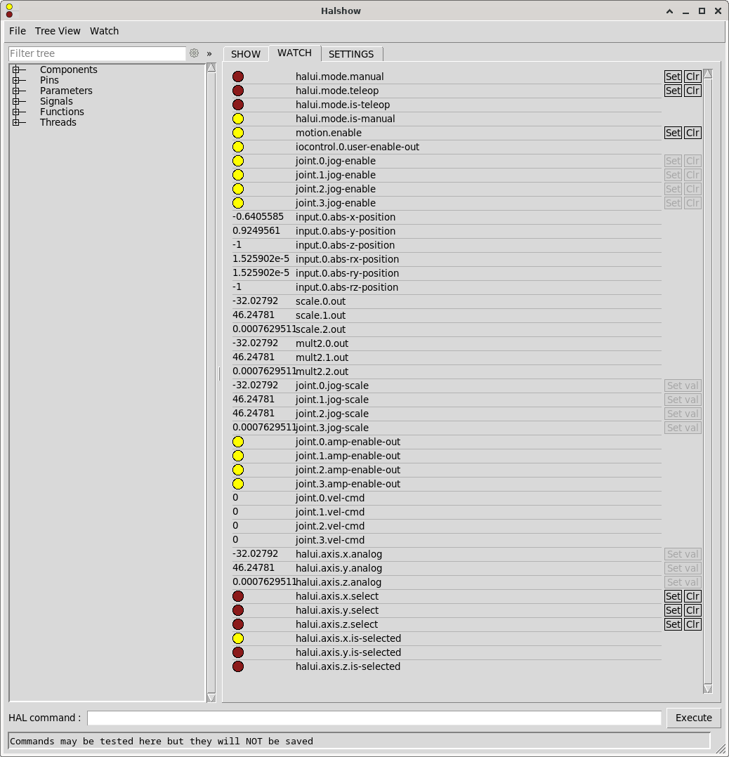
However, joint.*.vel-cmd always stays 0 and obviously the stepper motors are not spinning. Also I am not sure what mode I have to use, but I also tried setting halui.mode.manual and halui.mode.teleop using the [Set] button in halshow, but this did not change anything.
Setting it up like this will not allow the machine to start when the Xbox Controller is not connected as it expects the controller to be found. The controller will shut itself off if not being used for a certain period of time and this will also result in an error popping up in axis ui.
I think my current approach is way more complicated and clumsy than it actually needs to be, but the learning curve seems to be pretty steep for me and therefore I probably resorted to using way more AI generated code than I should have.
How do I
I am trying to set up my xbox controller to jog a three axis machine (y-gantry). Using a bluetooth dongle I had to fiddle around a bit (and install xpadneo) to get the controller to connect to the system but I eventually got there and do see input when pressing buttons/moving the joysticks.
I was digging into LinuxCNC a few years ago but then life happened and I had to put the project on ice up until now. This is my first home-built CNC (wood router) and I am very new to all of this.
My goal is to be able to move the X, Y (gantry) and Z axis using the gaming controller when there is no gcode being executed.
Currently this is a parport setup and the stepper motors are not actually installed on ball screws so I do not mess up anything while testing. I am planning on switching to a mesa card in the near future.
phew@linuxcnc:~$ sudo lsusb
Bus 001 Device 002: ID 2357:0604 TP-Link TP-Link Bluetooth USB Adapter
phew@linuxcnc:~$ sudo dkms status
hid-xpadneo/v0.9-226-ga16acb0, 6.1.0-39-rt-amd64, x86_64: installed
phew@linuxcnc:~$ sudo dmesg | grep -i xbox
[   41.033957] input: Xbox Wireless Controller as /devices/virtual/misc/uhid/0005:045E:0B13.0007/input/input16
[   41.034076] hid-generic 0005:045E:0B13.0007: input,hidraw6: BLUETOOTH HID v5.23 Gamepad [Xbox Wireless Controller] on 98:03:8e:4f:32:fd
[   41.094172] input: Xbox Wireless Controller as /devices/virtual/misc/uhid/0005:045E:0B13.0007/input/input17
[   41.094277] xpadneo 0005:045E:0B13.0007: input,hidraw6: BLUETOOTH HID v11.30 Gamepad [Xbox Wireless Controller] on 98:03:8e:4f:32:fd
[   41.094307] input: Xbox Wireless Controller Consumer Control as /devices/virtual/misc/uhid/0005:045E:0B13.0007/input/input18
[   41.094367] input: Xbox Wireless Controller Keyboard as /devices/virtual/misc/uhid/0005:045E:0B13.0007/input/input19
[   42.076531] xpadneo 0005:045E:0B13.0007: Xbox Wireless Controller [14:cb:65:c7:03:1e] connected
[   42.206305] input: Xbox Wireless Controller as /devices/virtual/misc/uhid/0005:045E:0B13.0007/input/input20
[   42.206585] xpadneo 0005:045E:0B13.0007: input,hidraw6: BLUETOOTH HID v11.30 Gamepad [Xbox Wireless Controller] on 98:03:8e:4f:32:fd
[   42.206615] input: Xbox Wireless Controller Consumer Control as /devices/virtual/misc/uhid/0005:045E:0B13.0007/input/input21
[   42.206743] input: Xbox Wireless Controller Keyboard as /devices/virtual/misc/uhid/0005:045E:0B13.0007/input/input22
[   43.189177] xpadneo 0005:045E:0B13.0007: Xbox Wireless Controller [14:cb:65:c7:03:1e] connected
xyyz.ini (machine basic setup)
# Generated by stepconf 1.1 at Thu Sep 11 20:35:55 2025
# If you make changes to this file, they will be
# overwritten when you run stepconf again

[EMC]
MACHINE = xyyz
DEBUG = 0
VERSION = 1.1

[DISPLAY]
DISPLAY = axis
EDITOR = gedit
POSITION_OFFSET = RELATIVE
POSITION_FEEDBACK = ACTUAL
ARCDIVISION = 64
GRIDS = 10mm 20mm 50mm 100mm 1in 2in 5in 10in
MAX_FEED_OVERRIDE = 1.2
MIN_SPINDLE_OVERRIDE = 0.5
MAX_SPINDLE_OVERRIDE = 1.2
DEFAULT_LINEAR_VELOCITY = 10.0
MIN_LINEAR_VELOCITY = 0
MAX_LINEAR_VELOCITY = 50.0
CYCLE_TIME = 0.100
INTRO_GRAPHIC = linuxcnc.gif
INTRO_TIME = 5
PROGRAM_PREFIX = /home/phew/linuxcnc/nc_files
INCREMENTS = 20mm 10mm 5mm 1mm .5mm .1mm .05mm .01mm .005mm

[KINS]
JOINTS = 4
KINEMATICS = trivkins coordinates=XYYZ kinstype=both

[FILTER]
PROGRAM_EXTENSION = .png,.gif,.jpg Greyscale Depth Image
PROGRAM_EXTENSION = .py Python Script
PROGRAM_EXTENSION = .nc,.tap G-Code File
png = image-to-gcode
gif = image-to-gcode
jpg = image-to-gcode
py = python

[TASK]
TASK = milltask
CYCLE_TIME = 0.010

[RS274NGC]
PARAMETER_FILE = linuxcnc.var

[EMCMOT]
EMCMOT = motmod
COMM_TIMEOUT = 1.0
BASE_PERIOD = 50000
SERVO_PERIOD = 1000000

[HAL]
HALUI = halui
HALFILE = xyyz.hal
HALFILE = custom.hal
HALFILE = xbox.hal
POSTGUI_HALFILE = postgui_call_list.hal
MDI_COMMAND = G0 X0
MDI_COMMAND = G0 Y0
MDI_COMMAND = G0 Z0
JOINT_0 = X
JOINT_1 = Y
JOINT_2 = Y
JOINT_3 = Z

[TRAJ]
COORDINATES =  X Y Y Z
LINEAR_UNITS = mm
ANGULAR_UNITS = degree
DEFAULT_LINEAR_VELOCITY = 2.50
MAX_LINEAR_VELOCITY = 25.00

[EMCIO]
EMCIO = io
CYCLE_TIME = 0.100
TOOL_TABLE = tool.tbl

[AXIS_X]
MAX_VELOCITY = 50.0
MAX_ACCELERATION = 25.0
MIN_LIMIT = -0.001
MAX_LIMIT = 800.0

[JOINT_0]
TYPE = LINEAR
HOME = 0.0
MIN_LIMIT = -0.001
MAX_LIMIT = 800.0
MAX_VELOCITY = 50.0
MAX_ACCELERATION = 1875.0
STEPGEN_MAXACCEL = 1875
SCALE = 160
FERROR = 1
MIN_FERROR = .25
HOME_SEQUENCE = 0
HOME_SEARCH_VEL = -20.0
HOME_LATCH_VEL = 2.0
HOME_OFFSET = -1.0
HOME_USE_INDEX = NO
HOME_IGNORE_LIMITS = YES

[AXIS_Y]
MAX_VELOCITY = 50.0
MAX_ACCELERATION = 25.0
MIN_LIMIT = -0.001
MAX_LIMIT = 1000.0

[JOINT_1]
TYPE = LINEAR
HOME = 0.0
MIN_LIMIT = -0.001
MAX_LIMIT = 1000.0
MAX_VELOCITY = 50.0
MAX_ACCELERATION = 1875.0
STEPGEN_MAXACCEL = 1875
SCALE = 160
FERROR = 1
MIN_FERROR = .25
HOME_SEQUENCE = 1
HOME_SEARCH_VEL = -20.0
HOME_LATCH_VEL = 2.0
HOME_OFFSET = -1.0
HOME_USE_INDEX = NO
HOME_IGNORE_LIMITS = YES

[JOINT_2]
TYPE = LINEAR
HOME = 0.0
MIN_LIMIT = -0.001
MAX_LIMIT = 1000.0
MAX_VELOCITY = 50.0
MAX_ACCELERATION = 1875.0
STEPGEN_MAXACCEL = 1875
SCALE = 160
FERROR = 1
MIN_FERROR = .25
HOME_SEQUENCE = 1
HOME_SEARCH_VEL = -20.0
HOME_LATCH_VEL = 2.0
HOME_OFFSET = -1.0
HOME_USE_INDEX = NO
HOME_IGNORE_LIMITS = YES

[AXIS_Z]
MAX_VELOCITY = 25.0
MAX_ACCELERATION = 10.0
MIN_LIMIT = -150.0
MAX_LIMIT = 0.001

[JOINT_3]
TYPE = LINEAR
HOME = 0.0
MIN_LIMIT = -150.0
MAX_LIMIT = 0.001
MAX_VELOCITY = 25.0
MAX_ACCELERATION = 1000.0
STEPGEN_MAXACCEL = 1875
SCALE = 160
FERROR = 1
MIN_FERROR = .25
HOME_SEQUENCE = 2
HOME_SEARCH_VEL = 20.0
HOME_LATCH_VEL = -2.0
HOME_OFFSET = 1.0
HOME_USE_INDEX = NO
HOME_IGNORE_LIMITS = YES
xyyz.hal:
loadrt [KINS]KINEMATICS kinstype=both
loadrt [EMCMOT]EMCMOT base_period_nsec=[EMCMOT]BASE_PERIOD servo_period_nsec=[EMCMOT]SERVO_PERIOD num_joints=[KINS]JOINTS
loadrt hal_parport cfg="1 out+in"
setp parport.0.reset-time 5000
loadrt stepgen step_type=0,0,0,0
loadrt pwmgen output_type=1

addf parport.0.read base-thread
addf stepgen.make-pulses base-thread
addf pwmgen.make-pulses base-thread
addf parport.0.write base-thread
addf parport.0.reset base-thread

addf stepgen.capture-position servo-thread
addf motion-command-handler servo-thread
addf motion-controller servo-thread
addf stepgen.update-freq servo-thread
addf pwmgen.update servo-thread

net x-home-raw parport.0.pin-11-in
net x-home-raw => joint.0.home-sw-in
#net x-home-raw => joint.0.neg-lim-sw-in
# net x-home-raw => joint.0.pos-lim-sw-in  # optional

net y0-home-raw parport.0.pin-12-in
net y0-home-raw => joint.1.home-sw-in
#net y0-home-raw => joint.1.neg-lim-sw-in

net y1-home-raw parport.0.pin-13-in
net y1-home-raw => joint.2.home-sw-in
#net y1-home-raw => joint.2.neg-lim-sw-in

net z-home-raw parport.0.pin-15-in
net z-home-raw => joint.3.home-sw-in
#net z-home-raw => joint.3.neg-lim-sw-in

setp stepgen.0.position-scale [JOINT_0]SCALE
setp stepgen.0.steplen 1
setp stepgen.0.stepspace 0
setp stepgen.0.dirhold 40000
setp stepgen.0.dirsetup 40000
setp stepgen.0.maxaccel [JOINT_0]STEPGEN_MAXACCEL
net xpos-cmd  joint.0.motor-pos-cmd => stepgen.0.position-cmd
net xpos-fb   stepgen.0.position-fb => joint.0.motor-pos-fb
net xstep     stepgen.0.step => parport.0.pin-02-out
net xdir      stepgen.0.dir  => parport.0.pin-03-out
net xenable   joint.0.amp-enable-out => stepgen.0.enable

net y-enable joint.1.amp-enable-out
net y-enable => stepgen.1.enable
net y-enable => stepgen.2.enable

setp stepgen.1.position-scale [JOINT_1]SCALE
setp stepgen.1.steplen 1
setp stepgen.1.stepspace 0
setp stepgen.1.dirhold 40000
setp stepgen.1.dirsetup 40000
setp stepgen.1.maxaccel [JOINT_1]STEPGEN_MAXACCEL
net ypos-cmd  joint.1.motor-pos-cmd => stepgen.1.position-cmd
net ypos-fb   stepgen.1.position-fb => joint.1.motor-pos-fb
net y0step    stepgen.1.step => parport.0.pin-04-out
net y0dir     stepgen.1.dir  => parport.0.pin-05-out

setp stepgen.2.position-scale [JOINT_2]SCALE
setp stepgen.2.steplen 1
setp stepgen.2.stepspace 0
setp stepgen.2.dirhold 40000
setp stepgen.2.dirsetup 40000
setp stepgen.2.maxaccel [JOINT_2]STEPGEN_MAXACCEL
net y1pos-cmd joint.2.motor-pos-cmd => stepgen.2.position-cmd
net y1pos-fb  stepgen.2.position-fb => joint.2.motor-pos-fb
net y1step    stepgen.2.step => parport.0.pin-06-out
net y1dir     stepgen.2.dir  => parport.0.pin-07-out

setp stepgen.3.position-scale [JOINT_3]SCALE
setp stepgen.3.steplen 1
setp stepgen.3.stepspace 0
setp stepgen.3.dirhold 40000
setp stepgen.3.dirsetup 40000
setp stepgen.3.maxaccel [JOINT_3]STEPGEN_MAXACCEL
net zpos-cmd joint.3.motor-pos-cmd => stepgen.3.position-cmd
net zpos-fb  stepgen.3.position-fb => joint.3.motor-pos-fb
net zstep    stepgen.3.step => parport.0.pin-08-out
net zdir     stepgen.3.dir  => parport.0.pin-09-out
net zenable  joint.3.amp-enable-out => stepgen.3.enable

net estop-out <= iocontrol.0.user-enable-out
net estop-out => iocontrol.0.emc-enable-in
xbox.hal
loadusr -W hal_input -KRAL Xbox

loadrt scale count=3
addf scale.0 servo-thread
addf scale.1 servo-thread
addf scale.2 servo-thread

setp scale.0.gain 50.0   # X
setp scale.1.gain 50.0   # Y
setp scale.2.gain 50.0   # Z

loadrt mult2 count=3
addf mult2.0 servo-thread
addf mult2.1 servo-thread
addf mult2.2 servo-thread

loadrt conv_bit_float
addf conv-bit-float.0 servo-thread

net xbox-x-raw input.0.abs-x-position => scale.0.in
net xbox-y-raw input.0.abs-y-position => scale.1.in
net xbox-z-raw input.0.abs-ry-position => scale.2.in

net xbox-x-scaled scale.0.out => mult2.0.in0
net xbox-y-scaled scale.1.out => mult2.1.in0
net xbox-z-scaled scale.2.out => mult2.2.in0

net xbox-jog-bit input.0.btn-a => conv-bit-float.0.in
net xbox-jog-float conv-bit-float.0.out => mult2.0.in1
net xbox-jog-float => mult2.1.in1
net xbox-jog-float => mult2.2.in1

net xbox-x-vel mult2.0.out => joint.0.jog-scale   # X
net xbox-y-vel mult2.1.out => joint.1.jog-scale   # Y (Y0)
net xbox-y-vel => joint.2.jog-scale                      # Y (Y1)
net xbox-z-vel mult2.2.out => joint.3.jog-scale   # Z

# Press [A]-button to enable joints
net xbox-jog-bit => joint.0.jog-enable
net xbox-jog-bit => joint.1.jog-enable
net xbox-jog-bit => joint.2.jog-enable
net xbox-jog-bit => joint.3.jog-enable

setp joint.0.jog-vel-mode TRUE
setp joint.1.jog-vel-mode TRUE
setp joint.2.jog-vel-mode TRUE
setp joint.3.jog-vel-mode TRUE

net xbox-x-vel => halui.axis.x.analog
net xbox-y-vel => halui.axis.y.analog
net xbox-z-vel => halui.axis.z.analog
With this setup I can see input from the controller in halshow:
However, joint.*.vel-cmd always stays 0 and obviously the stepper motors are not spinning. Also I am not sure what mode I have to use, but I also tried setting halui.mode.manual and halui.mode.teleop using the [Set] button in halshow, but this did not change anything.
Setting it up like this will not allow the machine to start when the Xbox Controller is not connected as it expects the controller to be found. The controller will shut itself off if not being used for a certain period of time and this will also result in an error popping up in axis ui.
I think my current approach is way more complicated and clumsy than it actually needs to be, but the learning curve seems to be pretty steep for me and therefore I probably resorted to using way more AI generated code than I should have.
How do I
- set this up correctly so the Xbox Controller input can actually controll the X, Y and Z axis?
- set this up in a way so the controller does not need to be connected in order for the machine to start and won't result in an error when the controller disconnects for some reason
- farmer_mike
- farmer_mike
12 Sep 2025 13:35 - 13 Sep 2025 01:36
Replied by farmer_mike on topic Getting (hopefully) close to an Rtelligent build
Getting (hopefully) close to an Rtelligent build
Category: EtherCAT
I have made some big progress lately. I have the limit switches and homing switches working. I also have the E stop working.
My issue is the RS750E AC servos shake quite a bit. Without the drive belts installed, the servos will sit and shake after completing a move. With the drive belts on, the system moves in the correct direction, but does so in a shaky manner.
My hypothesis is too much integral gain. I believe the problem is because I started with the stepper motor examples. Maybe there are some PID gains inside the drive that I need to configure.
I think what I need are the drive gains set with the SDO parameters inside the XML file.
Thanks for all the help
[/code]
[/code]
[/code]
My issue is the RS750E AC servos shake quite a bit. Without the drive belts installed, the servos will sit and shake after completing a move. With the drive belts on, the system moves in the correct direction, but does so in a shaky manner.
My hypothesis is too much integral gain. I believe the problem is because I started with the stepper motor examples. Maybe there are some PID gains inside the drive that I need to configure.
I think what I need are the drive gains set with the SDO parameters inside the XML file.
Thanks for all the help
###########################################################
#
# CIA 402 example snippet Hal
#
###########################################################

###########################################################
# Setup
###########################################################

loadrt [KINS]KINEMATICS
loadrt [EMCMOT]EMCMOT servo_period_nsec=[EMCMOT]SERVO_PERIOD num_joints=[KINS]JOINTS


loadusr -W lcec_conf ethercat-conf.xml
#loadusr -W /home/cnc/linuxcnc/configs/linuxcnc-cia402-single/python_control.py

loadrt lcec
loadrt cia402 count=3
loadrt pid names=0-pid,1-pid,2-pid

loadrt bitslice count=6 personality=32,32,32,32,32,32
addf bitslice.0 servo-thread
addf bitslice.1 servo-thread
addf bitslice.2 servo-thread
addf bitslice.3 servo-thread
addf bitslice.4 servo-thread
addf bitslice.5 servo-thread

loadrt conv_s32_u32 count=6
addf conv-s32-u32.0 servo-thread
addf conv-s32-u32.1 servo-thread
addf conv-s32-u32.2 servo-thread
addf conv-s32-u32.3 servo-thread
addf conv-s32-u32.4 servo-thread
addf conv-s32-u32.5 servo-thread


###########################################################
# Functions servo-thread
###########################################################

addf lcec.read-all servo-thread
addf cia402.0.read-all servo-thread
addf cia402.1.read-all servo-thread
addf cia402.2.read-all servo-thread

addf motion-command-handler servo-thread
addf motion-controller servo-thread

addf 0-pid.do-pid-calcs servo-thread
addf 1-pid.do-pid-calcs servo-thread
addf 2-pid.do-pid-calcs servo-thread

addf cia402.0.write-all servo-thread
addf cia402.1.write-all servo-thread
addf cia402.2.write-all servo-thread
addf lcec.write-all servo-thread


#########################################
#nets
#########################################
net emc-enable => iocontrol.0.emc-enable-in
sets emc-enable 1

#config


#
# Joint 0
#
setp cia402.0.csp-mode 1
setp cia402.0.pos-scale 786432


#from servo(ethercat) to cia402
net 0-statusword lcec.0.0.cia-statusword => cia402.0.statusword
net 0-opmode-display lcec.0.0.opmode-display => cia402.0.opmode-display
net 0-drv-act-pos lcec.0.0.actual-position => cia402.0.drv-actual-position
net 0-drv-act-velo lcec.0.0.actual-velocity => cia402.0.drv-actual-velocity

#from motion to cia

net 0-enable <= joint.0.amp-enable-out => cia402.0.enable
net 0-amp-fault => joint.0.amp-fault-in <= cia402.0.drv-fault
net 0-pos-cmd <= joint.0.motor-pos-cmd => cia402.0.pos-cmd
net 0-pos-fb => joint.0.motor-pos-fb <= cia402.0.pos-fb


#from cia402 to servo(ethercat)
net 0-controlword cia402.0.controlword => lcec.0.0.cia-controlword
net 0-modes-of-operation cia402.0.opmode => lcec.0.0.opmode
net 0-drv-target-pos cia402.0.drv-target-position => lcec.0.0.target-position
net 0-drv-target-velo cia402.0.drv-target-velocity => lcec.0.0.target-velocity


net my-out-0 conv-s32-u32.0.in <= lcec.0.0.digitalinputs
net my-in-0 conv-s32-u32.0.out => bitslice.0.in
net my-bit-0 bitslice.0.out-00 joint.0.neg-lim-sw-in

net my-out-0 conv-s32-u32.1.in <= lcec.0.0.digitalinputs
net my-in-1 conv-s32-u32.1.out => bitslice.1.in
net my-bit-1 bitslice.1.out-01 joint.0.pos-lim-sw-in

net my-out-0 conv-s32-u32.2.in <= lcec.0.0.digitalinputs
net my-in-2 conv-s32-u32.2.out => bitslice.2.in
net my-bit-2 bitslice.2.out-02 joint.0.home-sw-in


#
# Joint 1
#
setp cia402.1.csp-mode 1
setp cia402.1.pos-scale -786432

#from servo(ethercat) to cia402
net 1-statusword lcec.0.1.cia-statusword => cia402.1.statusword
net 1-opmode-display lcec.0.1.opmode-display => cia402.1.opmode-display
net 1-drv-act-pos lcec.0.1.actual-position => cia402.1.drv-actual-position
net 1-drv-act-velo lcec.0.1.actual-velocity => cia402.1.drv-actual-velocity

#from cia402 to servo(ethercat)
net 1-controlword cia402.1.controlword => lcec.0.1.cia-controlword
net 1-modes-of-operation cia402.1.opmode => lcec.0.1.opmode
net 1-drv-target-pos cia402.1.drv-target-position => lcec.0.1.target-position
net 1-drv-target-velo cia402.1.drv-target-velocity => lcec.0.1.target-velocity

#from motion to cia
net 1-enable <= joint.1.amp-enable-out => cia402.1.enable
net 1-amp-fault => joint.1.amp-fault-in <= cia402.1.drv-fault
net 1-pos-cmd <= joint.1.motor-pos-cmd => cia402.1.pos-cmd
net 1-pos-fb => joint.1.motor-pos-fb <= cia402.1.pos-fb


net my-out-1 conv-s32-u32.3.in <= lcec.0.1.digitalinputs
net my-in-3 conv-s32-u32.3.out => bitslice.3.in
net my-bit-3 bitslice.3.out-00 joint.1.pos-lim-sw-in

net my-out-1 conv-s32-u32.4.in <= lcec.0.1.digitalinputs
net my-in-4 conv-s32-u32.4.out => bitslice.4.in
net my-bit-4 bitslice.4.out-01 joint.1.neg-lim-sw-in

net my-out-1 conv-s32-u32.5.in <= lcec.0.1.digitalinputs
net my-in-5 conv-s32-u32.5.out => bitslice.5.in
net my-bit-5 bitslice.5.out-02 joint.1.home-sw-in


#
# Joint 2
#
setp cia402.2.csp-mode 1
setp cia402.2.pos-scale 96000

#from servo(ethercat) to cia402
net 2-statusword lcec.0.2.cia-statusword => cia402.2.statusword
net 2-opmode-display lcec.0.2.opmode-display => cia402.2.opmode-display
net 2-drv-act-pos lcec.0.2.actual-position => cia402.2.drv-actual-position
net 2-drv-act-velo lcec.0.2.actual-velocity => cia402.2.drv-actual-velocity

#from cia402 to servo(ethercat)
net 2-controlword cia402.2.controlword => lcec.0.2.cia-controlword
net 2-modes-of-operation cia402.2.opmode => lcec.0.2.opmode
net 2-drv-target-pos cia402.2.drv-target-position => lcec.0.2.target-position
net 2-drv-target-velo cia402.2.drv-target-velocity => lcec.0.2.target-velocity

#from motion to cia
net 2-enable <= joint.2.amp-enable-out => cia402.2.enable
net 2-amp-fault => joint.2.amp-fault-in <= cia402.2.drv-fault
net 2-pos-cmd <= joint.2.motor-pos-cmd => cia402.2.pos-cmd
net 2-pos-fb => joint.2.motor-pos-fb <= cia402.2.pos-fb

net 2-CCW-limit lcec.0.2.in-3 => joint.2.neg-lim-sw-in
net 2-CW-limit lcec.0.2.in-4 => joint.2.pos-lim-sw-in
net 2-in-home lcec.0.2.in-5 => joint.2.home-sw-in
net 2-in-6 lcec.0.2.in-6 => halui.estop.activate


#net spindle_speed spindle.0.speed-out => python_control.rpm_in
[code]# This config file was created 2020-08-14 17:19:37.621705 by the update_ini script
# The original config files may be found in the /home/demo/linuxcnc/configs/et-3ax/et_3ax_CIA402.old directory

[EMC]
# The version string for this INI file.
VERSION = 1.1

MACHINE = EtherCAT Machine
DEBUG = 1

[DISPLAY]
DISPLAY = axis
EDITOR = gedit

#PYVCP = pyvcp_panel.xml

# places the pyvcp panel at the bottom of the Axis window
PYVCP_POSITION = RIGHT

# Cycle time, in seconds, that display will sleep between polls
CYCLE_TIME =            0.100

# Path to help file
HELP_FILE =             doc/help.txt

# Initial display setting for position, RELATIVE or MACHINE
POSITION_OFFSET = RELATIVE
POSITION_FEEDBACK = ACTUAL
MAX_FEED_OVERRIDE = 1
# Prefix to be used
PROGRAM_PREFIX = /home/demo/linuxcnc/nc_files
INTRO_GRAPHIC = linuxcnc.gif
INTRO_TIME = 0
INCREMENTS = 1in .5in .25in .125in .0625in .025in .05in
#INCREMENTS = 5mm 1mm .5mm .1mm .05mm .01mm .005mm

[FILTER]
PROGRAM_EXTENSION = .png,.gif,.jpg Greyscale Depth Image
PROGRAM_EXTENSION = .py Python Script
png = image-to-gcode
gif = image-to-gcode
jpg = image-to-gcode
py = python
nc = /usr/bin/axis

[RS274NGC]

PARAMETER_FILE = linuxcnc.var

[EMCMOT]

EMCMOT = motmod
COMM_TIMEOUT = 1.0
BASE_PERIOD =  0
SERVO_PERIOD = 1000000

[TASK]
TASK = milltask
CYCLE_TIME = 0.005

[HAL]
HALFILE = cia402.hal
#SHUTDOWN = shutdown.hal
HALUI = halui

[HALUI]

[TRAJ]

HOME = 16 12 7
COORDINATES = XYZ
LINEAR_UNITS = in
ANGULAR_UNITS = deg
DEFAULT_LINEAR_VELOCITY = .25
MAX_LINEAR_VELOCITY = .5
MIN_LINEAR_VELOCITY = .01
DEFAULT_ANGULAR_VELOCITY = 360
MAX_ANGULAR_VELOCITY = 720
POSITION_FILE = position.txt

[EMCIO]

# Name of IO controller program, e.g., iov2 has tool changer stuff
EMCIO =         iov2

CYCLE_TIME =    0.100

# tool table file
TOOL_TABLE =    cia402.tbl
TOOL_CHANGE_POSITION = 0 0 50.8
#RANDOM_TOOLCHANGER = 1


[KINS]
JOINTS = 3
KINEMATICS = trivkins kinstype=both coordinates=xyz


[AXIS_X]
MIN_LIMIT = 0.1
MAX_LIMIT = 17.9
MAX_VELOCITY = .5
MAX_ACCELERATION = 10
BACKLASH = 0.0000

[JOINT_0]
TYPE = LINEAR
MAX_VELOCITY = .5
MAX_ACCELERATION = 10

DEADBAND = 0.01
P=1
I=0
D=0

# The values below should be 25% larger than MAX_VELOCITY and MAX_ACCELERATION
# If using BACKLASH compensation STEPGEN_MAXACCEL should be 100% larger.
# is this applicable for ethercat????
#STEPGEN_MAXVEL = 1.25
#STEPGEN_MAXACCEL = 1.25
SCALE = 1
FERROR = 200
MIN_FERROR = 50
MIN_LIMIT = 0
MAX_LIMIT = 18
HOME                    = 16
HOME_OFFSET                = 16
HOME_SEQUENCE            = 0

HOME_SEARCH_VEL = -.125
HOME_LATCH_VEL = -.125
HOME_USE_INDEX = NO
HOME_IGNORE_LIMITS        = NO


[AXIS_Y]
MIN_LIMIT = 0.1
MAX_LIMIT = 12.9
MAX_VELOCITY = .5
MAX_ACCELERATION = 10
BACKLASH = 0.0000


[JOINT_1]
TYPE = LINEAR
MAX_VELOCITY = .5
MAX_ACCELERATION = 10

DEADBAND = 0.01
P=1
I=0
D=0


# The values below should be 25% larger than MAX_VELOCITY and MAX_ACCELERATION
# If using BACKLASH compensation STEPGEN_MAXACCEL should be 100% larger.
# is this applicable for ethercat????
#STEPGEN_MAXVEL = 1.25
#STEPGEN_MAXACCEL = 1.25
STEP_SCALE = 1
FERROR = 2
MIN_FERROR = 20
MIN_LIMIT = 0
MAX_LIMIT = 13

HOME                    = 12
HOME_OFFSET                = 12
HOME_SEQUENCE            = 1

HOME_SEARCH_VEL = .125
HOME_LATCH_VEL = .125
HOME_USE_INDEX = NO
HOME_IGNORE_LIMITS        = NO


[JOINT_2]
TYPE = LINEAR
MAX_VELOCITY = .5
MAX_ACCELERATION = 10
# The values below should be 25% larger than MAX_VELOCITY and MAX_ACCELERATION
# If using BACKLASH compensation STEPGEN_MAXACCEL should be 100% larger.
# is this applicable for ethercat????
STEPGEN_MAXVEL = 1.25
STEPGEN_MAXACCEL = 1.25
STEP_SCALE = 1
FERROR = 200
MIN_FERROR = 20
MIN_LIMIT = 3.4
MAX_LIMIT = 8.1
HOME                    = 7
HOME_OFFSET                = 7
HOME_SEQUENCE            = 2

HOME_SEARCH_VEL = .125
HOME_LATCH_VEL = .125
HOME_USE_INDEX = NO
HOME_IGNORE_LIMITS    = NO


[AXIS_Z]
MIN_LIMIT = 3.5
MAX_LIMIT = 8
MAX_VELOCITY = .5
MAX_ACCELERATION = 10
BACKLASH = 0.0000
[/code]
[code][code]<masters>
  <master idx="0" appTimePeriod="1000000" refClockSyncCycles="1">


  <slave idx="0" type="generic" vid="00000A88" pid="0a880013" configPdos="true">
   <!-- Joint 0 -->
   <syncManager idx="0" dir="out"> </syncManager>
   <syncManager idx="1" dir="out"> </syncManager>
   <syncManager idx="2" dir="out">
    <pdo idx="1600">
     <pdoEntry idx="6040" subIdx="00" bitLen="16" halPin="cia-controlword" halType="u32"/>
     <pdoEntry idx="607a" subIdx="00" bitLen="32" halPin="target-position" halType="s32"/>
     <pdoEntry idx="60b8" subIdx="00" bitLen="16" halPin="touchprobefunction0" halType="bit"/>
    </pdo>
    <pdo idx="1601">
     <pdoEntry idx="6081" subIdx="00" bitLen="32" halPin="profile-velocity" halType="u32"/>
     <pdoEntry idx="6083" subIdx="00" bitLen="32" halPin="target-accel" halType="u32"/>
     <pdoEntry idx="6084" subIdx="00" bitLen="32" halPin="target-decel" halType="u32"/>
     <pdoEntry idx="6060" subIdx="00" bitLen="8" halPin="opmode" halType="s32"/>
    </pdo>
    <pdo idx="1602">
     <pdoEntry idx="60ff" subIdx="00" bitLen="32" halPin="target-velocity" halType="s32"/>
    </pdo>
   </syncManager>
   <syncManager idx="3" dir="in">
    <pdo idx="1a00">
     <pdoEntry idx="603f" subIdx="00" bitLen="16" halPin="errorcode" halType="bit"/>
     <pdoEntry idx="6041" subIdx="00" bitLen="16" halPin="cia-statusword" halType="u32"/>
     <pdoEntry idx="6061" subIdx="00" bitLen="8" halPin="opmode-display" halType="s32"/>
     <pdoEntry idx="6064" subIdx="00" bitLen="32" halPin="actual-position" halType="s32"/>
     <pdoEntry idx="60b9" subIdx="00" bitLen="16" halPin="touchprobestat" halType="bit"/>
     <pdoEntry idx="60ba" subIdx="00" bitLen="32" halPin="touchprobe1pos" halType="s32"/>
     <pdoEntry idx="60fd" subIdx="00" bitLen="32" halPin="digitalinputs" halType="s32"/>
    </pdo>
    <pdo idx="1a01">
     <pdoEntry idx="606c" subIdx="00" bitLen="32" halPin="actual-velocity" halType="s32"/>
    </pdo>
   </syncManager>
   <dcConf assignActivate="300" sync0Cycle="1000000"/>
  </slave>


  <slave idx="1" type="generic" vid="00000A88" pid="0a880013" configPdos="true">
   <!-- Joint 1 -->
   <syncManager idx="0" dir="out"> </syncManager>
   <syncManager idx="1" dir="out"> </syncManager>
   <syncManager idx="2" dir="out">
    <pdo idx="1600">
     <pdoEntry idx="6040" subIdx="00" bitLen="16" halPin="cia-controlword" halType="u32"/>
     <pdoEntry idx="607a" subIdx="00" bitLen="32" halPin="target-position" halType="s32"/>
     <pdoEntry idx="60b8" subIdx="00" bitLen="16" halPin="touchprobefunction0" halType="bit"/>
    </pdo>
    <pdo idx="1601">
     <pdoEntry idx="6081" subIdx="00" bitLen="32" halPin="profile-velocity" halType="u32"/>
     <pdoEntry idx="6083" subIdx="00" bitLen="32" halPin="target-accel" halType="u32"/>
     <pdoEntry idx="6084" subIdx="00" bitLen="32" halPin="target-decel" halType="u32"/>
     <pdoEntry idx="6060" subIdx="00" bitLen="8" halPin="opmode" halType="s32"/>
    </pdo>
    <pdo idx="1602">
     <pdoEntry idx="60ff" subIdx="00" bitLen="32" halPin="target-velocity" halType="s32"/>
    </pdo>
   </syncManager>
   <syncManager idx="3" dir="in">
    <pdo idx="1a00">
     <pdoEntry idx="603f" subIdx="00" bitLen="16" halPin="errorcode" halType="bit"/>
     <pdoEntry idx="6041" subIdx="00" bitLen="16" halPin="cia-statusword" halType="u32"/>
     <pdoEntry idx="6061" subIdx="00" bitLen="8" halPin="opmode-display" halType="s32"/>
     <pdoEntry idx="6064" subIdx="00" bitLen="32" halPin="actual-position" halType="s32"/>
     <pdoEntry idx="60b9" subIdx="00" bitLen="16" halPin="touchprobestat" halType="bit"/>
     <pdoEntry idx="60ba" subIdx="00" bitLen="32" halPin="touchprobe1pos" halType="s32"/>
     <pdoEntry idx="60fd" subIdx="00" bitLen="32" halPin="digitalinputs" halType="s32"/>
    </pdo>
    <pdo idx="1a01">
     <pdoEntry idx="606c" subIdx="00" bitLen="32" halPin="actual-velocity" halType="s32"/>
    </pdo>
   </syncManager>
   <dcConf assignActivate="300" sync0Cycle="1000000"/>
  </slave>

     <!-- Joint 2 -->
    <slave idx="2" type="generic" vid="00000a88" pid="0a880002" configPdos="true">
      <dcConf assignActivate="300" sync0Cycle="*1" sync0Shift="0"/>
      <sdoConfig idx="2000" subIdx="0"><sdoDataRaw data ="88 13"/></sdoConfig>  <!-- Max motor current (5.0) -->
      <sdoConfig idx="2007" subIdx="3"><sdoDataRaw data ="01"/></sdoConfig>     <!-- Input 3 - CCW Limit -->
      <sdoConfig idx="2007" subIdx="4"><sdoDataRaw data ="02"/></sdoConfig>     <!-- Input 4 - CW Limit -->
      <sdoConfig idx="2007" subIdx="5"><sdoDataRaw data ="03"/></sdoConfig>     <!-- Input 5 - Home Function -->
      <sdoConfig idx="2007" subIdx="6"><sdoDataRaw data ="05"/></sdoConfig>     <!-- Input 6 - Emergency Stop -->
      <sdoConfig idx="2011" subIdx="0"><sdoDataRaw data ="01 00"/></sdoConfig>  <!-- Closed loop -->
      <sdoConfig idx="6098" subIdx="0"><sdoDataRaw data ="11 00"/></sdoConfig>  <!-- Home mode 17 -->
      <sdoConfig idx="607C" subIdx="0"><sdoDataRaw data ="00 00"/></sdoConfig>  <!-- Home offset 0  -->
      <sdoConfig idx="609A" subIdx="0"><sdoDataRaw data ="F4 01"/></sdoConfig>  <!-- Home accelleration 500 -->
      <sdoConfig idx="6099" subIdx="01"><sdoDataRaw data ="C4 09"/></sdoConfig>  <!-- Home fast speed 2500-->
      <sdoConfig idx="6099" subIdx="02"><sdoDataRaw data ="F4 01"/></sdoConfig>  <!-- Home slow speed 500 -->
      <syncManager idx="2" dir="out">
        <pdo idx="1600">
          <pdoEntry idx="6040" subIdx="00" bitLen="16" halPin="cia-controlword" halType="u32"/>
          <pdoEntry idx="6060" subIdx="00" bitLen="8" halPin="opmode" halType="s32"/>
          <!-- Target Position -->
          <pdoEntry idx="607A" subIdx="00" bitLen="32" halPin="target-position" halType="s32"/>
          <!-- Target Velocity -->
          <pdoEntry idx="60FF" subIdx="00" bitLen="32" halPin="target-velocity" halType="s32"/>
          <!-- Digtial Outputs (manufacturer's extension ECT86/ECT60)-->
          <pdoEntry idx="204A" subIdx="0" bitLen="16" halType="complex">
            <complexEntry bitLen="1" halPin="out-1" halType="bit"/>
            <complexEntry bitLen="1" halPin="out-2" halType="bit"/>
            <complexEntry bitLen="14"/>
          </pdoEntry>
        </pdo>
      </syncManager>
      <syncManager idx="3" dir="in">
        <pdo idx="1a00">
          <pdoEntry idx="6041" subIdx="00" bitLen="16" halPin="cia-statusword" halType="u32"/>
          <pdoEntry idx="6061" subIdx="00" bitLen="8" halPin="opmode-display" halType="s32"/>
          <pdoEntry idx="6064" subIdx="00" bitLen="32" halPin="actual-position" halType="s32"/>
          <pdoEntry idx="606C" subIdx="00" bitLen="32" halPin="actual-velocity" halType="s32"/>
          <pdoEntry idx="6077" subIdx="00" bitLen="32" halPin="actual-torque" halType="s32"/>
          <!-- Digtial_inputs (cia402 compatible) -->
          <pdoEntry idx="60FD" subIdx="0" bitLen="32" halType="complex">
            <complexEntry bitLen="1" halPin="CW-limit" halType="bit"/>
            <complexEntry bitLen="1" halPin="CCW-limit" halType="bit"/>
            <complexEntry bitLen="1" halPin="in-home" halType="bit"/>
            <complexEntry bitLen="13"/>
            <complexEntry bitLen="1" halPin="in-1" halType="bit"/>
            <complexEntry bitLen="1" halPin="in-2" halType="bit"/>
            <complexEntry bitLen="1" halPin="in-3" halType="bit"/>
            <complexEntry bitLen="1" halPin="in-4" halType="bit"/>
            <complexEntry bitLen="1" halPin="in-5" halType="bit"/>
            <complexEntry bitLen="1" halPin="in-6" halType="bit"/>
            <complexEntry bitLen="10"/>
          </pdoEntry>
        </pdo>
      </syncManager>
    </slave>


  </master>
</masters>
[/code]
- Martin.L
- Martin.L
06 Sep 2025 12:18
Replied by Martin.L on topic Stepperonline A6-1000EC driver
Stepperonline A6-1000EC driver
Category: EtherCAT
replace x with your servo/spindle index
net s-vel-cmd <= spindle.0.speed-out
net s-vel-cmd => cia402.x.velocity-cmd
You will need csp mode 0 :
setp cia402.5.csp-mode 0
setp cia402.5.pos-scale 1
net s-vel-cmd <= spindle.0.speed-out
net s-vel-cmd => cia402.x.velocity-cmd
You will need csp mode 0 :
setp cia402.5.csp-mode 0
setp cia402.5.pos-scale 1
- Rookie0
- Rookie0
01 Sep 2025 11:44
hope it helps.
Replied by Rookie0 on topic Stepperonline A6-1000EC driver
Stepperonline A6-1000EC driver
Category: EtherCAT
# spindle.hal
# use cia402 comp.  link: https://github.com/dbraun1981/hal-cia402
loadrt cia402 names=cia-s
addf cia-s.read-all           servo-thread
addf cia-s.write-all          servo-thread
# value = resolution_servo_encoder ÷ 60
# if gearbox exists, then * reduction_ratio(input:ouput)
setp cia-s.velo-scale 800
net s-statusword      <= lcec.0.N.cia-statusword   => cia-s.statusword
net s-opmode-display  <= lcec.0.N.opmode-display   => cia-s.opmode-display
net s-drv-act-velo    <= lcec.0.N.actual-velocity  => cia-s.drv-actual-velocity
net s-controlword     <= cia-s.controlword         => lcec.0.N.cia-controlword
net s-opmode          <= cia-s.opmode              => lcec.0.N.opmode
net s-drv-target-velo <= cia-s.drv-target-velocity => lcec.0.N.target-velocity
net s-enable          <= spindle.0.on              => cia-s.enable
net s-velo-fb         <= cia-s.velocity-fb         => spindle.0.speed-in
net s-velo-cmd        <= spindle.0.speed-out       => cia-s.velocity-cmd
hope it helps.
- russkinch

01 Sep 2025 11:14
Stepperonline A6-1000EC driver was created by russkinch
Stepperonline A6-1000EC driver
Category: EtherCAT
Hi again. I have sorted the power issue (manual was no help at all). Now, I have it set to Linuxcnc using ethercat. It is all communication etc. I want to run the servo as a spindle motor so just have the target-velocity (60FE). How do I create the 'pins' to tell the drive to turn at say 1000rpm with an M3 command is given. I have done the many times using a VFD (much easier but space and weight limits force me to use a servo).
I am soooo out of my depth here, any help is always hugely appreciated. (I have already looked through the various threads and found no help after hours of scrolling)
I am soooo out of my depth here, any help is always hugely appreciated. (I have already looked through the various threads and found no help after hours of scrolling)
Time to create page: 0.792 seconds