Search Results (Searched for: )
- myankov
- myankov
31 Jul 2026 12:50
") .
.- viewsat
- viewsat
31 Jul 2026 12:29
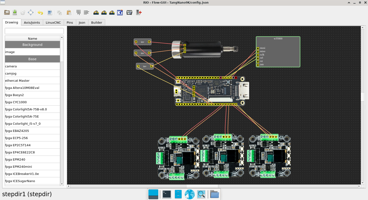
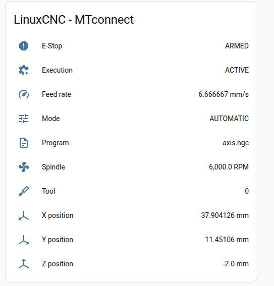
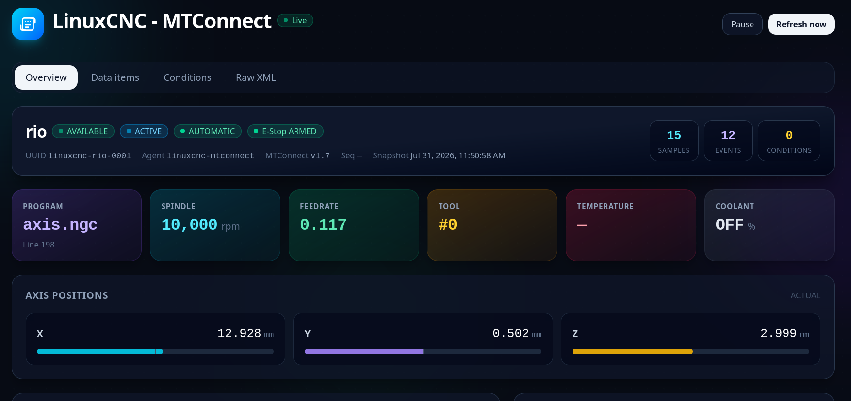
Replied by viewsat on topic LinuxCNC-RIO - RealtimeIO for LinuxCNC based on FPGA (ICE40 / ECP5)
LinuxCNC-RIO - RealtimeIO for LinuxCNC based on FPGA (ICE40 / ECP5)
Category: Computers and Hardware
- meister
- meister
31 Jul 2026 12:24
Replied by meister on topic LinuxCNC-RIO - RealtimeIO for LinuxCNC based on FPGA (ICE40 / ECP5)
LinuxCNC-RIO - RealtimeIO for LinuxCNC based on FPGA (ICE40 / ECP5)
Category: Computers and Hardware
- viewsat
- viewsat
31 Jul 2026 12:23 - 31 Jul 2026 16:00
Replied by viewsat on topic LinuxCNC-RIO - RealtimeIO for LinuxCNC based on FPGA (ICE40 / ECP5)
LinuxCNC-RIO - RealtimeIO for LinuxCNC based on FPGA (ICE40 / ECP5)
Category: Computers and Hardware
- hitchhiker
- hitchhiker
31 Jul 2026 11:42
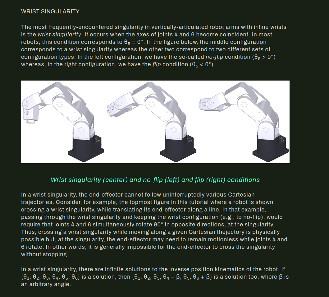
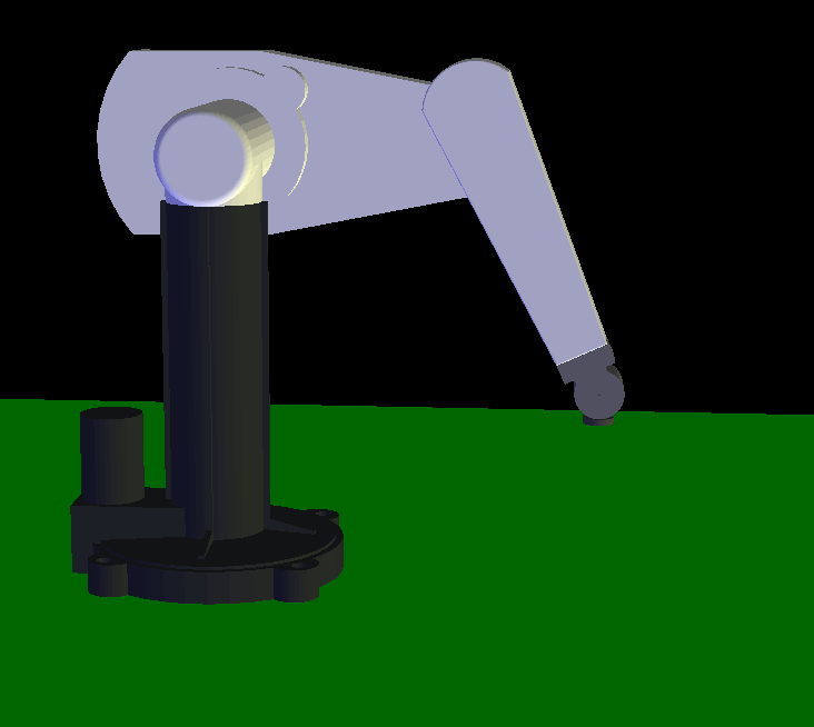
Replied by hitchhiker on topic PUMA 200 Robotarm and some Hal/INI issues
PUMA 200 Robotarm and some Hal/INI issues
Category: Advanced Configuration
- rodw

31 Jul 2026 11:16
- Todd Zuercher

31 Jul 2026 11:02
Replied by Todd Zuercher on topic RS485 + Absolute Encoder for Homing a 4th Axis?
RS485 + Absolute Encoder for Homing a 4th Axis?
Category: General LinuxCNC Questions
- meister
- meister
31 Jul 2026 09:49 - 31 Jul 2026 09:57
- rodw
31 Jul 2026 09:46

- rodw
31 Jul 2026 09:40
- rodw
31 Jul 2026 09:26
- Aciera

31 Jul 2026 07:46 - 31 Jul 2026 08:20
Replied by Aciera on topic PUMA 200 Robotarm and some Hal/INI issues
PUMA 200 Robotarm and some Hal/INI issues
Category: Advanced Configuration
- meister
- meister
31 Jul 2026 07:34
- Jugo2
- Jugo2
31 Jul 2026 07:22 - 31 Jul 2026 07:23
- Logthor
- Logthor
31 Jul 2026 07:19
Time to create page: 0.938 seconds