Advanced Search

Search Results (Searched for: )

  • PCW
  • PCW's Avatar
13 Aug 2024 02:56
Replied by PCW on topic 7i77 watch dog catch 22

7i77 watch dog catch 22

Category: Driver Boards

A 7I77 watchdog fault occurs when communication with LinuxCNC is lost.
This is not something you typically recover from without restarting
LinuxCNC, that is, it usually means LinuxCNC or the host PC has crashed.
or host communication to the FPGA card has been lost or serial communications
have been lost

 
  • Benb
  • Benb's Avatar
13 Aug 2024 01:50
7i77 watch dog catch 22 was created by Benb

7i77 watch dog catch 22

Category: Driver Boards

Question 1:
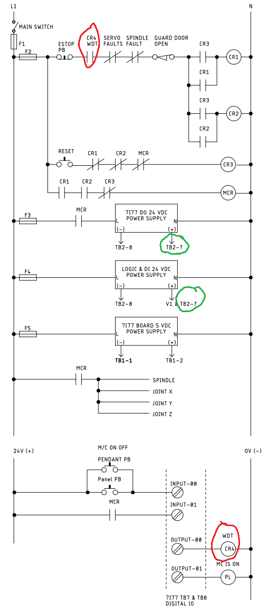
Is there an output pin for an external Estop/reset safety circuit to read the status of 7i77 WDT? If not, would it be feasible to use one of the existing pin outputs by Keeping this output pin ON while the watchdog timer has NOT bit. Here where the catch 22 comes into play, when the WDT bites, the hostmot2 driver disables the digital outputs therefore my external hardwired circuit will not be able to determine the WDT output pin status (see diagram Highlighted in RED). One way I can think of to solve this puzzle is to restrict the WDT from internally disabling the digital outputs, and have WDT just set a flag and let the hardwired safety circuit take care of disabling the power to the digital outputs.       Or I am out to lunch?Question 2:
7i77 field terminal block has several terminals I am hoping to be able to keep the field power OFF to the digital outputs until the safety lockout circuit is reset and the field digital inputs and VIN powered while the ESTOP circuit is active. If you look at the wiring diagram, I need the numbers of the terminal blocks marked with question mark (highlited in green). Nomenclature:
CR# – CONTROL RELAY
MCR - MASTER CONTROL RELAY
F# - FUSE
DI – DIGITAL INPUT
DO – DIGITAL OUTPUT
PB – PUSH BUTTON
WDT – WATCH DOG TIMER
L1 - MAIN SUPPLY LINE 120 VAC
N - MAIN SUPPLY NEUTRAL
PL- Pilot Light
A brief explanation to what this hardwired circuit does follows this diagram.
  The wiring circuit diagram below  is a hardwired circuit that will allow power to be removed from digital outputs, servos and spindle. The circuit achieves the following:
  • If power is lost during operation the machine will not restart when power is re-established.
  • If an Estop is activated or a fault occurs during operation, the circuit will inhibit (prevent) power to digital outputs, servos and spindle. The rest of the machine control circuit will stay in the ON state; this will enable you to troubleshoot and resume operation without major reinitialization of the machine.
  • Machine will not restart until all faults are corrected and operator presses reset button.
This hardwired circuit is the equivalent of safety relay without guided contacts.
  • PCW
  • PCW's Avatar
13 Aug 2024 01:23 - 13 Aug 2024 01:59
Replied by PCW on topic RCpwmgen

RCpwmgen

Category: Driver Boards

I would expect you use a scale of 180
and get 90 degrees for a value of 90 (2 ms width)
and -90 degrees for a value of -90  (1 ms width)

You could also set the offset to 1 and then use a 0..180 value
to get 1 to 2 ms
  • Project_Hopeless
  • Project_Hopeless's Avatar
13 Aug 2024 01:10
Replied by Project_Hopeless on topic RCpwmgen

RCpwmgen

Category: Driver Boards

After some time away I got this working with the 7i96_5abobrcd firmware.  The physical pins DB25 vs. HAL pins had me twisted around.
setp hm2_[MESA](BOARD).0.rcpwmgen.rate 50setp hm2_[MESA](BOARD).0.rcpwmgen.00.width 1
setp hm2_[MESA](BOARD).0.rcpwmgen.00.offset 1.5
setp hm2_[MESA](BOARD).0.rcpwmgen.00.scale 180

Just a general question, on this function.  To get the servo to physically rotate 180 degrees (+-90) I need a scale of 95.  180 gave ~90degrees, and 90 gave ~190-200 degrees. Is this just the variability of the servo potentiometer?

 
  • tommylight
  • tommylight's Avatar
13 Aug 2024 00:56
Replied by tommylight on topic OLD Lathe conversion to a CNC

OLD Lathe conversion to a CNC

Category: Turning

Whatever size you can put the cable through and do at least 1 or 2 windings.
  • tommylight
  • tommylight's Avatar
13 Aug 2024 00:53
Replied by tommylight on topic Joint Amplifier Fault on Non-Moving Axis

Joint Amplifier Fault on Non-Moving Axis

Category: Basic Configuration

I would venture a guess at interference and check that first with a scope or a DVM that has a min/max memory feature.
  • JamesHoward
  • JamesHoward
13 Aug 2024 00:48

ColorCNC Colorlight 5A-75E/5A-75B as FPGA controller board

Category: Driver Boards

I made a header board for 5A-75E8.2 and started testing the litexcnc firmware and encountered the following problems.
1- When I close the linuxcnc software or press the estop key, the motors start moving.
2- For homing using encoder z pulse, after receiving the z pulse instead of stopping, it makes a strange movement at full speed and then stops.
I posted this problem before but couldn't find a solution for it.
Does anyone have any suggestions for solving these problems?

I cant say anything to problem 2, but as for problem #1:

Are you trying to use software for an e-stop? This is a terrible idea! IMO anyways. An E-stop Should cut power to your drives AND send a stop signal to your software. (one exception is: sending an e-stop signal to your spindle. if you cut power it will spin down for a long time. if you send it an e-stop signal it should stop almost instantly)
  • Benb
  • Benb's Avatar
12 Aug 2024 22:52
Replied by Benb on topic MCG Server Controller for 4th axis

MCG Server Controller for 4th axis

Category: Driver Boards

The dc servo motor you have is fine and can be used to operate with Linuxcnc. You need either an analog (+-10vdc) or digital (pul/dir) brushed dc servo drive. I use Copley Junus (analog drive) for digital drive Leadshine DC810 is a popular digital servo drive (I have no experience with these drives) both the Copley and the Leadshine require a dc servo power supply. I have seen on EBAY Advance Motion Control drives with built in dc power supply. Since your servo motor is low current and standard voltage you should be able to find what you need on EBAY.
In nut shell you need to match your current Mesa hardware with either analog or digital servo drive. Then start looking for the drive that match your servo motor.
Good luck Ben
  • cakeslob
  • cakeslob
12 Aug 2024 22:40
Replied by cakeslob on topic Remora for RP2040

Remora for RP2040

Category: Computers and Hardware

limo, I saw you in the discord the otherday I think, you arent using the rp2040 right?

Is remora capable of doing it? Most likely, so long as you stay within the parameters of the remora board you are using, by which I mean, if your stepgen steprate is too high, remora might not be able to accommodate. Otherwise it sounds like a standard affair, as just configuring a stepgen.

Do we know how to configure a spindle with step/dir with remora? I dont personally. The bulk of it will be linuxcnc, and we can help you with connecting to remora
  • rodw
  • rodw's Avatar
12 Aug 2024 21:23
  • Mecanix
  • Mecanix
12 Aug 2024 21:04
Replied by Mecanix on topic Y axis configuration

Y axis configuration

Category: General LinuxCNC Questions

Yeah can be confusing those MIN/MAX, pos/neg, sensors, logic levels, it's endless. Took me a while to set-up my mill correctly back when I've introduced Lcnc to it.

Shout out if you're stuck. Pleasure btw, be safe and have fun.
  • cakeslob
  • cakeslob
12 Aug 2024 21:04

Remora - ethernet NVEM / EC300 / EC500 cnc board

Category: Computers and Hardware

{
"Thread": "Servo",
"Type": "Digital Pin",
"Comment": "IN03",
"Pin": "P4_21",
"Mode": "Input",
"Data Bit": 6,
"Invert": "True"
},
 
"Comment": "IN03", = what its labeled as on the board
" "Pin": "P4_21"," = Physical pin assignment on the MCU
"Data Bit": 6, = Remora/HAL pin assignment
Meanwile....in the halfile
net X_HOME remora.input.06 => joint.0.home-sw-in = remora.input.06 is IN3 is P4_21 , is connected to j.0.home which should be homeswitch for joint0 which is usually x.

I dont see home switch in any of the actual rt1052 halfiles though, so thats probably why you cant find the,
  • Ismacr63
  • Ismacr63
12 Aug 2024 20:56
Replied by Ismacr63 on topic Y axis configuration

Y axis configuration

Category: General LinuxCNC Questions

#*** AXIS_Y *******************************
[AXIS_Y]
MIN_LIMIT = 0
MAX_LIMIT = 144
MIN_LIMIT = -144
MAX_LIMIT = 0

[JOINT_1]
MIN_LIMIT = 0
MAX_LIMIT = 144
MIN_LIMIT = -144
MAX_LIMIT = 0

Rename attachement keybingdings.py.txt to keybingdings.py
Place into your /config/ folder.

Hope this helps.


It works but i have had to change HOME_OFFSET
HOME_SEARCH_VEL
HOME_LATCH_VEL

for positive values and everything perfect.

I think the same thing is going to happen to me with the X and Z axes.

When I install the limit sensors
i will test it and comment.

thank you so much.
  • cakeslob
  • cakeslob
12 Aug 2024 20:56

Remora - ethernet NVEM / EC300 / EC500 cnc board

Category: Computers and Hardware

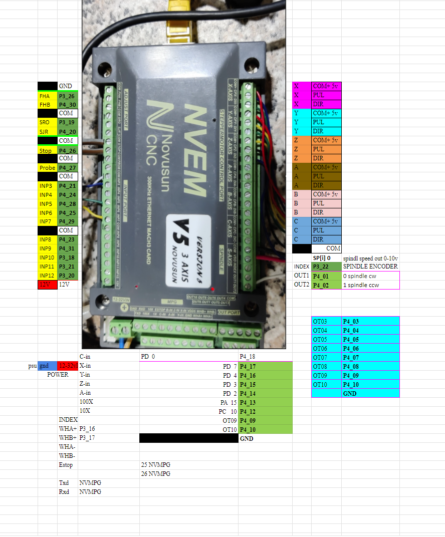
Hi pin outputs you can find in the attachment.
Estop has 2 pins, same for probe. Other inputs have one common and one negative for each input. 


Hey, dont use this one if you have the RT1052, i dont even know how yours is still working if youve been using that one. The one you keep posting is for the STM32 version of the NVEM. use this one by raf

oK lads I have got made a thing. :)

Hope this will help somehow 
Pinout NVEM v5 RT1052 Remora firmware config pinout
 

  • Mecanix
  • Mecanix
12 Aug 2024 20:47

LinuxCNC-RIO - RealtimeIO for LinuxCNC based on FPGA (ICE40 / ECP5)

Category: Computers and Hardware

Ah f.it, changed my mind. We'll do another board if/when we'll need more/all pins. Larger PCB, wider connector pitch, VFD analog + Relay, etc etc. 

a.k.a Production-level "LinuxCNC-RIO - RealtimeIO Motion Control Board"

Let's get a solid prototype out and tested first. Sending this out as-is. I NEED THIS PCB BACK ASAP loool
Displaying 23236 - 23250 out of 25033 results.
Time to create page: 0.686 seconds
Powered by Kunena Forum