- Hardware & Machines
- Computers and Hardware
- LinuxCNC-RIO - RealtimeIO for LinuxCNC based on FPGA (ICE40 / ECP5)
LinuxCNC-RIO - RealtimeIO for LinuxCNC based on FPGA (ICE40 / ECP5)
- meister
- Offline
- Platinum Member
-

Less
More
- Posts: 745
- Thank you received: 465
12 Aug 2024 12:15 #307543
by meister
Replied by meister on topic LinuxCNC-RIO - RealtimeIO for LinuxCNC based on FPGA (ICE40 / ECP5)
fixed in the dev branchOnly source code I've had to change was for the board family to be recognized as a its high-speed C7/i6 type.
/riocore/riocore/boards/MecanixDev/board.json
[-] "family": "GW1N-9C",
[+] "family": "GW1N-9C7",
/riocore/riocore/generator/toolchains/gowin/toolchain.py
Line 103:
[+] if family == "GW1N-9C7":
[+] prj_data.append(f' <Device name="{family_gowin}" pn="{ftype}">gw1nr9c-017</Device>')
That was the reason my PIN03, PIN13, PIN 15 (high speed bank) was not working. The Gowin was always compiling for a C6/I5 fpga type
But allpins works now!!

The following user(s) said Thank You: Mecanix
Please Log in or Create an account to join the conversation.
- Mecanix
- Offline
- Platinum Member
-
Less
More
- Posts: 447
- Thank you received: 227
12 Aug 2024 17:01 #307566
by Mecanix

Replied by Mecanix on topic LinuxCNC-RIO - RealtimeIO for LinuxCNC based on FPGA (ICE40 / ECP5)
Before sending this out to the pcb fab, and out of fear this would have been too good to be true, I've set my function generator to 'noise' and beaten up an input with the oscope trigger set to catch a low level. It did after a few seconds. Be pleased to know your advice was taken, I've added 20K pupps on the inputsI'm going to have to disagree with you on the need for pull up or pull down resistors on inputs, especially with switches (unless the switch is switching to either zero or 5v)and rotary encoder that have an open collector output. Without a pullup or pull down resistor the input is going to float, until that input has a definite logic level on it. With high impedance inputs it requires very very little current to switch the input, if the voltage is at the right level. Generally on a chip such as the venerable 74xx245 when the enable inputs are in the disable state the output is considered to be in a "high impedance state" and is unable to "drive" the outputs.
Honestly any input that is connected via a cable needs a pullup or pulldown resistor for the case of a breakage in the signal wire, especially with an MPG, if teh signal wire breaks you want that input at the board end to held at a known level. The last thing you want is for your input to pick up stray noise and start oscillating. The chip wont "know" if it is a legitimate signal or noise and will pass that on to the other side.
That's why sometimes I feel am opto isolator is a bit better in this respect as the current required to drive the LED in normal situations is a little higher than induced noise in the line.
Never in my life have I designed a digital circuit that takes external off board signals with pullup or pulldown resistors, or inputs that get the input from a SPST switch from an on board switch without a pullup or pull down.
The following user(s) said Thank You: kostas, rthorntn, meister
Please Log in or Create an account to join the conversation.
- meister
- Offline
- Platinum Member
-
Less
More
- Posts: 745
- Thank you received: 465
12 Aug 2024 20:22 #307590
by meister
Replied by meister on topic LinuxCNC-RIO - RealtimeIO for LinuxCNC based on FPGA (ICE40 / ECP5)
if you still have io-pins free on the FPGA, put them on test-pads if you can, you can always use them
Please Log in or Create an account to join the conversation.
- Mecanix
- Offline
- Platinum Member
-
Less
More
- Posts: 447
- Thank you received: 227
12 Aug 2024 20:34 - 12 Aug 2024 20:35 #307591
by Mecanix
Fine if I just leave them at their 3V3 logic level? Test pins assuming, [USE WITH CARE, pirate skull logo near lol]

Replied by Mecanix on topic LinuxCNC-RIO - RealtimeIO for LinuxCNC based on FPGA (ICE40 / ECP5)
Ok, I'll delay the pcb fab a day and see what I can do with those lonely 15 GPIOs. I'll have them all via and TP on the back side of the PCB.if you still have io-pins free on the FPGA, put them on test-pads if you can, you can always use them
Fine if I just leave them at their 3V3 logic level? Test pins assuming, [USE WITH CARE, pirate skull logo near lol]
Last edit: 12 Aug 2024 20:35 by Mecanix.
Please Log in or Create an account to join the conversation.
- Mecanix
- Offline
- Platinum Member
-
Less
More
- Posts: 447
- Thank you received: 227
12 Aug 2024 20:47 #307593
by Mecanix
Replied by Mecanix on topic LinuxCNC-RIO - RealtimeIO for LinuxCNC based on FPGA (ICE40 / ECP5)
Ah f.it, changed my mind. We'll do another board if/when we'll need more/all pins. Larger PCB, wider connector pitch, VFD analog + Relay, etc etc.
a.k.a Production-level "LinuxCNC-RIO - RealtimeIO Motion Control Board"
Let's get a solid prototype out and tested first. Sending this out as-is. I NEED THIS PCB BACK ASAP loool
a.k.a Production-level "LinuxCNC-RIO - RealtimeIO Motion Control Board"
Let's get a solid prototype out and tested first. Sending this out as-is. I NEED THIS PCB BACK ASAP loool
The following user(s) said Thank You: meister, samueldutradasilva
Please Log in or Create an account to join the conversation.
- Mecanix
- Offline
- Platinum Member
-
Less
More
- Posts: 447
- Thank you received: 227
13 Aug 2024 12:51 #307628
by Mecanix
Replied by Mecanix on topic LinuxCNC-RIO - RealtimeIO for LinuxCNC based on FPGA (ICE40 / ECP5)
It's Official. Left to PCB fab an hour ago and so I should receive this badboy in 5~7days. Looking forward enjoying LinuxCNC-RIO over traced hardware (farewell jumper wires and cheap modules, at last). My very first "True Isolated" motion control board!!
The following user(s) said Thank You: kostas, rthorntn, tommylight, Clive S, meister
Please Log in or Create an account to join the conversation.
- rthorntn
- Offline
- Junior Member
-

Less
More
- Posts: 33
- Thank you received: 6
13 Aug 2024 21:35 - 13 Aug 2024 21:36 #307664
by rthorntn
Replied by rthorntn on topic LinuxCNC-RIO - RealtimeIO for LinuxCNC based on FPGA (ICE40 / ECP5)
Awesome, did you use any opto-couplers/digital isolators, are the nine 16-pin IC's only level-shifters?
Last edit: 13 Aug 2024 21:36 by rthorntn.
Please Log in or Create an account to join the conversation.
- Mecanix
- Offline
- Platinum Member
-
Less
More
- Posts: 447
- Thank you received: 227
14 Aug 2024 00:05 #307685
by Mecanix
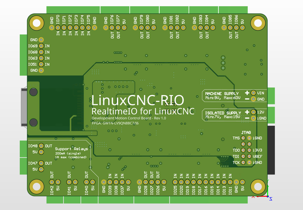
Here's the cool visuals:


Replied by Mecanix on topic LinuxCNC-RIO - RealtimeIO for LinuxCNC based on FPGA (ICE40 / ECP5)
Well spotted, correct, those 9 parts are indeed the level shifting. Features digital isolation also, all in one part. I apologize for omitting the schematic for now, once I have it cleaned up and arranged I'll put it up. I'd like to test the board prior though. Regardless, here's a visual below of how it's arranged (ten inputs). Additionally, I'm getting us an ultra-low ripple Isolated 12V Supply done for that board. Plugs right on the main. If we are to isolate this FPGA/Motion Control thing, might as well isolate it true & properly!!Awesome, did you use any opto-couplers/digital isolators, are the nine 16-pin IC's only level-shifters?
Here's the cool visuals:
The following user(s) said Thank You: rthorntn, meister
Please Log in or Create an account to join the conversation.
- rthorntn
- Offline
- Junior Member
-
Less
More
- Posts: 33
- Thank you received: 6
14 Aug 2024 23:18 #307755
by rthorntn
Replied by rthorntn on topic LinuxCNC-RIO - RealtimeIO for LinuxCNC based on FPGA (ICE40 / ECP5)
Thanks!
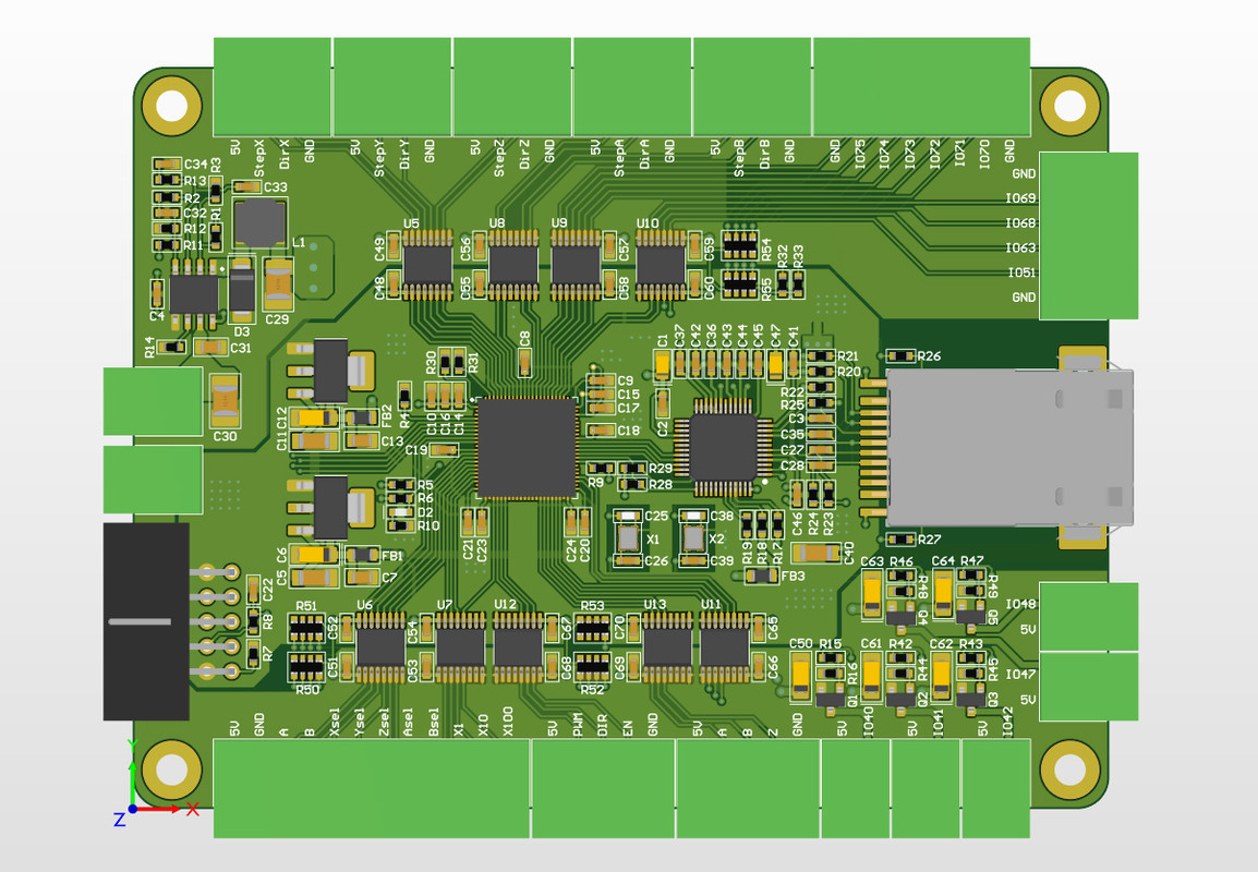
Just trying to work this out in my head, to learn...30 shifted and isolated I/O pins (20 inputs 10 outputs, up to 36 supported (4 x 9)), using ISO7760, so are you just doing a 180 degree on the iso7760 depending on whether it covers inputs or outputs?
How do you plan to solder this, paste and a wee oven?
The following user(s) said Thank You: Mecanix
Please Log in or Create an account to join the conversation.
- Mecanix
- Offline
- Platinum Member
-
Less
More
- Posts: 447
- Thank you received: 227
15 Aug 2024 00:48 #307758
by Mecanix
Using Sn63Pb37 solder paste and a hot plate for assembly. I know I know, lead based [DANGER]. Notice no parts on the bottom of the PCB, and so the process is stencil, paste-on, and flat-on a hot plate @230dC for 2.5min it goes. Yields 100% rate each and every time.
(You can prolly guess I'm looking forward that board!!)
Replied by Mecanix on topic LinuxCNC-RIO - RealtimeIO for LinuxCNC based on FPGA (ICE40 / ECP5)
Correct again! That iso776x part will switch to specs if powered within 2V5~5V in either direction, as you've guessed already. Can even go down to 1V2 (seems to work) although speed is not guaranteed. On the Ins/Outs; I'm counting 18 OUTPUTs & 23 INPUTs on that board, with 5 outputs having 200mA support - useful for switching analog relays on/off (Oiler, Coolant, Clamp, Lighting, Spare). All in All plenty sufficient to build any machine-tool to manufacture a spacecraft!!Thanks!
Just trying to work this out in my head, to learn...30 shifted and isolated I/O pins (20 inputs 10 outputs, up to 36 supported (4 x 9)), using ISO7760, so are you just doing a 180 degree on the iso7760 depending on whether it covers inputs or outputs?
How do you plan to solder this, paste and a wee oven?
Using Sn63Pb37 solder paste and a hot plate for assembly. I know I know, lead based [DANGER]. Notice no parts on the bottom of the PCB, and so the process is stencil, paste-on, and flat-on a hot plate @230dC for 2.5min it goes. Yields 100% rate each and every time.
(You can prolly guess I'm looking forward that board!!)
The following user(s) said Thank You: kostas, rthorntn, meister
Please Log in or Create an account to join the conversation.
- Hardware & Machines
- Computers and Hardware
- LinuxCNC-RIO - RealtimeIO for LinuxCNC based on FPGA (ICE40 / ECP5)
Time to create page: 1.263 seconds