Search Results (Searched for: )
- besriworld
- besriworld
08 Sep 2024 15:47
Replied by besriworld on topic Fanuc 2S AC spindle motor on Delta C2000+
Fanuc 2S AC spindle motor on Delta C2000+
Category: Milling Machines
- Mtndrew77
- Mtndrew77
08 Sep 2024 15:40
Replied by Mtndrew77 on topic Threading with A B phase only?
Threading with A B phase only?
Category: General LinuxCNC Questions
- spumco
- spumco
08 Sep 2024 15:06 - 08 Sep 2024 15:08
Probe Basic - startup error on new installation was created by spumco
Probe Basic - startup error on new installation
Category: QtPyVCP
- tommylight

08 Sep 2024 15:05
- tommylight
08 Sep 2024 15:01
Replied by tommylight on topic USB ports quit working?
USB ports quit working?
Category: Installing LinuxCNC
")
- tommylight
08 Sep 2024 14:56
Replied by tommylight on topic Mesa 7i96 Output Wiring
Mesa 7i96 Output Wiring
Category: Driver Boards
- tommylight
08 Sep 2024 14:51
- tommylight
08 Sep 2024 14:49
Replied by tommylight on topic What do you really get for a $350 desk top engraver ?
What do you really get for a $350 desk top engraver ?
Category: Show Your Stuff
- spumco
- spumco
08 Sep 2024 14:49
Replied by spumco on topic USB ports quit working?
USB ports quit working?
Category: Installing LinuxCNC
- ekbiker
- ekbiker
08 Sep 2024 14:48
- swepeter
- swepeter
08 Sep 2024 14:40
Replied by swepeter on topic Mesa 7i96 Output Wiring
Mesa 7i96 Output Wiring
Category: Driver Boards
- PCW

08 Sep 2024 14:29
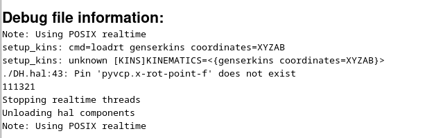
- Aciera

08 Sep 2024 14:28
Replied by Aciera on topic Using a HAL pin in DH parameters
Using a HAL pin in DH parameters
Category: HAL
- PCW
08 Sep 2024 14:26
- Abdulkareem
- Abdulkareem
08 Sep 2024 14:25
Replied by Abdulkareem on topic Using a HAL pin in DH parameters
Using a HAL pin in DH parameters
Category: HAL
Time to create page: 0.471 seconds