Search Results (Searched for: estop_latch)
- tuxcnc
- tuxcnc
25 Mar 2025 18:52
Replied by tuxcnc on topic Remora - ethernet NVEM / EC300 / EC500 cnc board
Remora - ethernet NVEM / EC300 / EC500 cnc board
Category: Computers and Hardware
- rodw

23 Feb 2025 07:36
- tommylight

23 Feb 2025 00:29
- rodw
23 Feb 2025 00:05
- MTTI

17 Feb 2025 08:16
Replied by MTTI on topic New and Working RTAI debs for 2.9
New and Working RTAI debs for 2.9
Category: Installing LinuxCNC
- tommylight
14 Feb 2025 19:37
Replied by tommylight on topic Remora - ethernet NVEM / EC300 / EC500 cnc board
Remora - ethernet NVEM / EC300 / EC500 cnc board
Category: Computers and Hardware
- rodw
16 Jan 2025 07:56 - 16 Jan 2025 07:57
Replied by rodw on topic First Start Up - E Stops
First Start Up - E Stops
Category: General LinuxCNC Questions
- notJamesLee
- notJamesLee
16 Jan 2025 04:06
Replied by notJamesLee on topic First Start Up - E Stops
First Start Up - E Stops
Category: General LinuxCNC Questions
- notJamesLee
- notJamesLee
15 Jan 2025 06:10 - 15 Jan 2025 16:50
Replied by notJamesLee on topic First Start Up - E Stops
First Start Up - E Stops
Category: General LinuxCNC Questions
- rodw
15 Jan 2025 03:00
Replied by rodw on topic First Start Up - E Stops
First Start Up - E Stops
Category: General LinuxCNC Questions
- Benb

29 Dec 2024 04:18
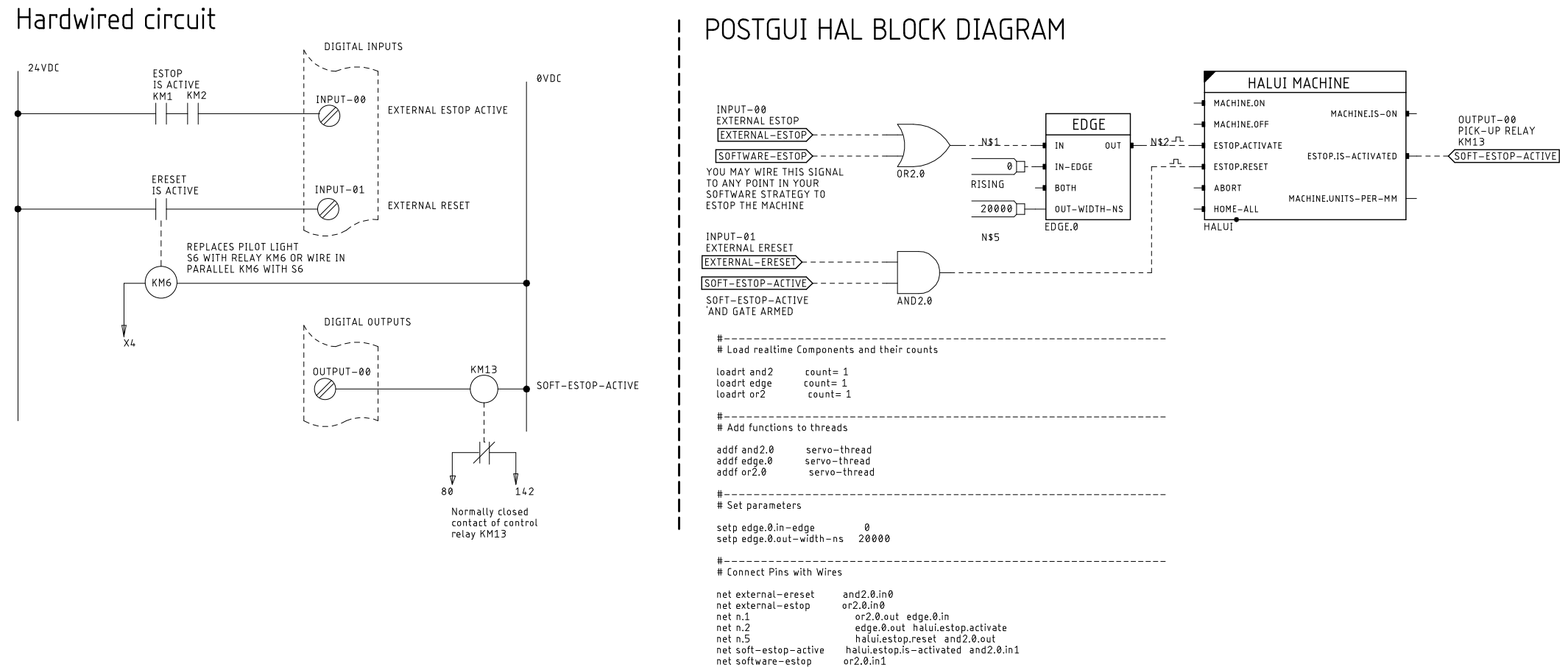
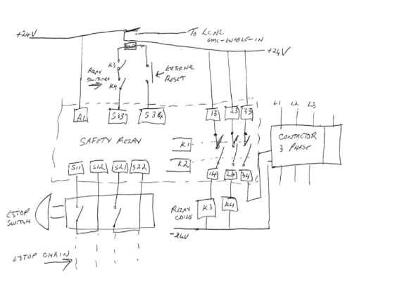
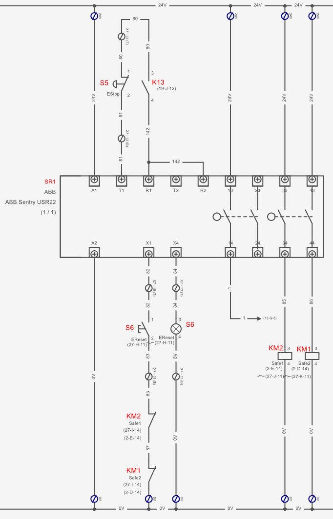
Replied by Benb on topic Physical safety relay and software estop latch working together?
Physical safety relay and software estop latch working together?
Category: HAL
- thomaseg
- thomaseg
28 Dec 2024 09:19
Replied by thomaseg on topic Physical safety relay and software estop latch working together?
Physical safety relay and software estop latch working together?
Category: HAL
- Benb
27 Dec 2024 01:10
Replied by Benb on topic Physical safety relay and software estop latch working together?
Physical safety relay and software estop latch working together?
Category: HAL
- rodw
26 Dec 2024 05:22
Replied by rodw on topic Physical safety relay and software estop latch working together?
Physical safety relay and software estop latch working together?
Category: HAL
- thomaseg
- thomaseg
25 Dec 2024 21:44 - 25 Dec 2024 21:48
Physical safety relay and software estop latch working together? was created by thomaseg
Physical safety relay and software estop latch working together?
Category: HAL

Time to create page: 1.016 seconds