Hello

After almost 4 months of no news, I am able to give you further details and insights on the retrofit. In the meantime, we received a new machine (KUKA KR15-2 KRC2) which required a little bit of maintenance, and we were in need of some maintenance too, in the form of holidays
. In the remaining time in between, all electronics of the control cabinet were removed (only the Indramat and the corresponding transformers have stayed) and the ancient components were replaced. Due to the new variable frequency drive, most of the original electronics weren't needed anymore. Therefore, a whole rebuild of the cabinet was the most logical thing to do.
By now, all components are wired in and the cabinet only needs a cleanup. We decided to build and wire all safety related components into EK1914 and EL1918 TwinSafe terminals. One of the EK1914 safety outputs drives a PILZ PNOZ s7 safety relais, which inturn cuts power to all "dangerous" output terminals. After the safety program is finished, all components of the mill can be tested. We did not test the communication between the TwinSafe PLC and LinuxCNC beforehand, so let's see how that will turn out
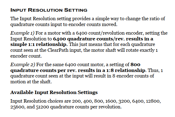
For now, the cabinet is mostly finished and just in need of a cleanup.We are also using the aforementioned modified EL5021 terminals for the X, Y, and Z glass scales. Due to their minimum interpolation setting of 10 bit (=1024), we are theoretically able to read each 20 µm glass scale down to a resolution of around 20 nm. We do not believe that we are actually that accurate by any means, but we are indeed able to register every single move of each axis. Even if it is just caused by a finger pressing slightly on an axis. In the hot summer months, we also saw the mill getting bigger/smaller due to thermal expansion.
Our very first implementation of a homing component dedicated to Beckhoff encoder inputs is also working, granted not 100% as expected. The bugs still need to be fixed. Our installed VFD also needs to be tested. It interlocks the contactor for the hydraulic system opening the tool changer and vice versa. An inductive sensor is also mounted on the fan side of the spindle motor, which sends 2 pulses for every revolution of the motor shaft. These pulses are counted by the VFD for a potential PID loop in the future. It is also equipped with a brake resistor, which should allow us to cut some serious threads with rigid tapping by using the original gearbox. Speaking of which, that also needs to be tested. It received its own 16 channel input card and two EL7332 motor driver terminals to drive all three motors.
There still needs to be some serious work done, but we are getting there
If you want further details, just let me know and i will send you some details as soon as possible