
Search Results (Searched for: )
- ContinenteCNC
18 Nov 2025 23:55 - 18 Nov 2025 23:57
Replied by ContinenteCNC on topic Axis Modifications
This is a mod that allows using a single key to cycle through Program Run, Program Pause, and Program Resume.
I unbound the keys R, P, and S from their original commands and bound only the R key to a routine that handles the cycling.
If you’re willing to test it, please let me know if something doesn’t work correctly and I’ll fix it.
I unbound the keys R, P, and S from their original commands and bound only the R key to a routine that handles the cycling.
If you’re willing to test it, please let me know if something doesn’t work correctly and I’ll fix it.
- Cooped-Up
18 Nov 2025 23:50
Replied by Cooped-Up on topic Maho MH800e Retrofit Project
I swapped around the inputs and outputs and that solved the issue. I was able to get all the buttons to function. I spent a while working on getting the gmoccapy jog buttons to move the axis but for some reason the only way I was able to get any of the axis to move outside of homing is to use the halshow to select the axis for jogging. Tried tying the ui pins to the pos and neg axis pins. Also almost done with the pendant with the mpg just need the rotary switches and wiring
- ContinenteCNC
18 Nov 2025 23:47 - 19 Nov 2025 00:05
Replied by ContinenteCNC on topic Axis Modifications
This is a mod for incrementally increasing/decreasing Feed, Rapid, and Spindle Overrides.
They behave similarly to the Jog Speed slider.
I unbound the keys `, 1, 2, 3, 4, 5, 6, 7, 8, 9, 0
And bound:
1, 2 to decrease/increase Feed Override
3, 4 to decrease/increase Rapid Override
5, 6 to decrease/increase Spindle Override
Keys `, 7, 8, 9, 0 have no effect.
It follows the INI fine settings.
I have also implemented an exponential response to speed up changes. In principle, it works with any exponent, but so far I’ve had the best results with power = 3.0.
If you want linear behavior, set power = 1.0, and then each key press will change the value by one unit.
If for some reason a slider gets stuck at a certain value, set linear_threshold_rate to a value slightly higher than the stuck position. That will solve the issue.
It’s not as quick as a potentiometer, but it works quite well. If you want it to be even faster, try:
xset r rate 250 40
This doubles the key auto-repeat rate and cuts the delay before auto-repeat starts in half.
Try different delay and rate values. The downside is that if you set them too high, editing text files can feel awkward.
If you’re willing to test it, please let me know if something doesn’t work correctly and I’ll fix it.
By the way, this mod is derived from this post: forum.linuxcnc.org/51-ot-posts/49830-com...ntrol-console#279421
They behave similarly to the Jog Speed slider.
I unbound the keys `, 1, 2, 3, 4, 5, 6, 7, 8, 9, 0
And bound:
1, 2 to decrease/increase Feed Override
3, 4 to decrease/increase Rapid Override
5, 6 to decrease/increase Spindle Override
Keys `, 7, 8, 9, 0 have no effect.
It follows the INI fine settings.
I have also implemented an exponential response to speed up changes. In principle, it works with any exponent, but so far I’ve had the best results with power = 3.0.
If you want linear behavior, set power = 1.0, and then each key press will change the value by one unit.
If for some reason a slider gets stuck at a certain value, set linear_threshold_rate to a value slightly higher than the stuck position. That will solve the issue.
It’s not as quick as a potentiometer, but it works quite well. If you want it to be even faster, try:
xset r rate 250 40
This doubles the key auto-repeat rate and cuts the delay before auto-repeat starts in half.
Try different delay and rate values. The downside is that if you set them too high, editing text files can feel awkward.
If you’re willing to test it, please let me know if something doesn’t work correctly and I’ll fix it.
By the way, this mod is derived from this post: forum.linuxcnc.org/51-ot-posts/49830-com...ntrol-console#279421
- tcbmetalworks
18 Nov 2025 23:44
Replied by tcbmetalworks on topic Looking for a freelancer to assist in drawing schematics for cnc plasma table
I wrote this up in chat gpt pretty quickly I think it just about covers all of the bases here of the project.
CNC Plasma Table – Electrical & Wiring Requirements
Project: Remote design of electrical system + wiring documentation for LinuxCNC plasma table
Client: TCB Metal Works
1. Project Overview
You will remotely design the complete electrical and control system for a custom CNC plasma cutting table powered by LinuxCNC.
You will create:
Complete wiring diagram set (schematic + physical routing)
Full Bill of Materials (BOM) with real part numbers
Wire gauge, shielding, grounding, and EMI mitigation plan
Bulkhead connector list + panel layout
Mesa board selection + full LinuxCNC I/O map
Integration notes for all components
Testing & commissioning checklist
This is a 100% remote engineering job — no physical inspection of hardware is required.
2. Available Power Sources
Near the machine:
220 VAC available
460 VAC available
No dedicated 110/120 VAC, which must be generated using a control transformer if needed
Engineer must design the incoming power strategy and transformer selection.
3. Motion Hardware
3.1 X & Y Axis – AC Servos (Provided)
3× A6 Series 1000W RS485 AC Servo Motor Kits
3000 rpm
3.18 Nm
17-bit absolute encoder
IP67 motors
Axis layout:
Y axis: 2 servos (dual-drive gantry)
X axis: 1 servo
Notes:
Motor-to-drive cables are already supplied by the manufacturer.
You do not need to design or evaluate those cables.
Engineer must:
Design AC mains wiring to each servo drive
Design control, enable, alarm, and ESTOP signal wiring between drives and Mesa
Include needed fuses, breakers, filters, and terminals
Provide cabinet layout and routing plan
Include proper grounding and shielding recommendations
3.2 Z Axis – Stepper Motor (Needs Driver + Cable)
PV267-D2.8AA stepper motor — Oriental Motor
Stepper driver not provided
Stepper motor cable not provided
Engineer must:
Select a compatible stepper driver suitable for PV267-D2.8AA + LinuxCNC step/dir
Define driver voltage supply requirements
Design:
Step/Dir wiring from Mesa
Motor wiring from driver to Z motor
Required cable shielding, gauge, and insulation
Connector type and strain relief
4. Control Electronics (Mesa + Power)
Engineer must select Mesa hardware capable of supporting:
3× servo axes
1× stepper axis
THC-AD
Ohmic sensing
All limit/floating switches
Plasma start / Arc OK
E-stop & safety I/O
Deliverables:
Recommended Mesa board combination (e.g., 7i76E, 7i96S, 7i85, THCAD, etc.)
Justification for chosen hardware
Complete LinuxCNC I/O mapping
Required DC power supplies (24V / 5V / others)
Proper AC distribution, fuses, breakers, and protection devices
5. Torch Height & Ohmic Sensing
5.1 THC-AD Integration
Engineer must design:
Raw arc voltage wiring from Hypertherm HT2000 to THC-AD
THC-AD signal wiring to Mesa
Required shielding and filtering
Scaling notes for LinuxCNC
5.2 Ohmic Sensing (Planned)
Engineer must:
Recommend a compatible ohmic board
Provide wiring diagram for torch → ohmic board → Mesa
Specify cable type and shielding
Document signal polarity & behavior
6. Hypertherm HT2000 Integration
Engineer must design wiring for:
Required signals
Torch start / trigger
Arc OK
Raw arc voltage (+/–) into THC-AD
Required protection
Isolation (if needed)
Surge suppression
Filtering
EMI protection
Routing rules
Arc voltage wiring must be kept separate from low-voltage control wiring
7. Limit Switches & Floating Head
X Axis
2 limit switches:
X-min
X-max
Y Axis (Dual Gantry Drive)
2 limit switches:
Y-min
Y-max
Engineer must propose a reliable gantry squaring / homing method for the two Y motors.
Z Axis
2 end-of-travel limit switches:
Z-min
Z-max
1 floating-head switch (touch-off)
Engineer must:
Select appropriate switch type (mechanical or prox)
Provide wiring diagrams to Mesa
Specify wire gauge, shielding, and cable routing
Provide LinuxCNC input mapping
Include any debouncing/filtering requirements
8. Wiring, Shielding, & EMI
Engineer must specify:
Wire gauges for:
AC mains
Servo drive feeds
Stepper driver feeds
Stepper motor wiring
Limit/floating/ohmic wires
Plasma signals
DC supply lines
Shielding requirements for:
Step/dir
Limits/floating/ohmic
Arc voltage
THC-AD lines
EMI considerations
Cable separation
Ferrite locations
Filtering recommendations
9. Grounding & Bonding
The engineer must design the grounding/bonding approach.
Important physical detail:
The water table, gantry, and control cabinet are three separate physical assemblies.
The engineer must account for this when designing:
Grounding/bonding layout
EMC/EMI mitigation
Plasma return path considerations
Ohmic sensing grounding
No grounding method (star, bus, single-point, etc.) is mandated — the engineer chooses the correct approach.
10. Control Cabinet & Bulkheads
Engineer must design:
Cabinet Layout
AC distribution, transformers, PSUs
Mesa boards
Servo drives
Stepper driver
Fuses, breakers, contactors
DIN rail layout
Ventilation/fans
Bulkhead Connectors
Used wherever practical for:
Servo cables (using glands or pass-throughs)
Z stepper cable
Limit/floating switches
Ohmic sensing
Plasma start / Arc OK
E-stop / operator controls
Ethernet access
Engineer must specify:
Connector type
Pinout
Panel cutout style
Labeling
11. Documentation Package
Engineer must deliver:
11.1 Wiring Diagram Set
Full schematic
Cabinet wiring
Field wiring
Power distribution
Grounding/bonding
Bulkhead connector pinouts
11.2 BOM
Complete list of:
Mesa hardware
Stepper driver
Transformers / PSUs
Switches
Connectors
Wire/cable
Protection devices
Cabinet hardware
11.3 I/O Map
All LinuxCNC inputs/outputs
Axis definitions
THC/ohmic mappings
E-stop & safety signals
11.4 Commissioning Checklist
Power-up verification
Servo enable/jog
Stepper test
Homing / gantry squaring
Z floating-head test
Plasma start / Arc OK
THC test
Ohmic test
EMI/noise checks
CNC Plasma Table – Electrical & Wiring Requirements
Project: Remote design of electrical system + wiring documentation for LinuxCNC plasma table
Client: TCB Metal Works
1. Project Overview
You will remotely design the complete electrical and control system for a custom CNC plasma cutting table powered by LinuxCNC.
You will create:
Complete wiring diagram set (schematic + physical routing)
Full Bill of Materials (BOM) with real part numbers
Wire gauge, shielding, grounding, and EMI mitigation plan
Bulkhead connector list + panel layout
Mesa board selection + full LinuxCNC I/O map
Integration notes for all components
Testing & commissioning checklist
This is a 100% remote engineering job — no physical inspection of hardware is required.
2. Available Power Sources
Near the machine:
220 VAC available
460 VAC available
No dedicated 110/120 VAC, which must be generated using a control transformer if needed
Engineer must design the incoming power strategy and transformer selection.
3. Motion Hardware
3.1 X & Y Axis – AC Servos (Provided)
3× A6 Series 1000W RS485 AC Servo Motor Kits
3000 rpm
3.18 Nm
17-bit absolute encoder
IP67 motors
Axis layout:
Y axis: 2 servos (dual-drive gantry)
X axis: 1 servo
Notes:
Motor-to-drive cables are already supplied by the manufacturer.
You do not need to design or evaluate those cables.
Engineer must:
Design AC mains wiring to each servo drive
Design control, enable, alarm, and ESTOP signal wiring between drives and Mesa
Include needed fuses, breakers, filters, and terminals
Provide cabinet layout and routing plan
Include proper grounding and shielding recommendations
3.2 Z Axis – Stepper Motor (Needs Driver + Cable)
PV267-D2.8AA stepper motor — Oriental Motor
Stepper driver not provided
Stepper motor cable not provided
Engineer must:
Select a compatible stepper driver suitable for PV267-D2.8AA + LinuxCNC step/dir
Define driver voltage supply requirements
Design:
Step/Dir wiring from Mesa
Motor wiring from driver to Z motor
Required cable shielding, gauge, and insulation
Connector type and strain relief
4. Control Electronics (Mesa + Power)
Engineer must select Mesa hardware capable of supporting:
3× servo axes
1× stepper axis
THC-AD
Ohmic sensing
All limit/floating switches
Plasma start / Arc OK
E-stop & safety I/O
Deliverables:
Recommended Mesa board combination (e.g., 7i76E, 7i96S, 7i85, THCAD, etc.)
Justification for chosen hardware
Complete LinuxCNC I/O mapping
Required DC power supplies (24V / 5V / others)
Proper AC distribution, fuses, breakers, and protection devices
5. Torch Height & Ohmic Sensing
5.1 THC-AD Integration
Engineer must design:
Raw arc voltage wiring from Hypertherm HT2000 to THC-AD
THC-AD signal wiring to Mesa
Required shielding and filtering
Scaling notes for LinuxCNC
5.2 Ohmic Sensing (Planned)
Engineer must:
Recommend a compatible ohmic board
Provide wiring diagram for torch → ohmic board → Mesa
Specify cable type and shielding
Document signal polarity & behavior
6. Hypertherm HT2000 Integration
Engineer must design wiring for:
Required signals
Torch start / trigger
Arc OK
Raw arc voltage (+/–) into THC-AD
Required protection
Isolation (if needed)
Surge suppression
Filtering
EMI protection
Routing rules
Arc voltage wiring must be kept separate from low-voltage control wiring
7. Limit Switches & Floating Head
X Axis
2 limit switches:
X-min
X-max
Y Axis (Dual Gantry Drive)
2 limit switches:
Y-min
Y-max
Engineer must propose a reliable gantry squaring / homing method for the two Y motors.
Z Axis
2 end-of-travel limit switches:
Z-min
Z-max
1 floating-head switch (touch-off)
Engineer must:
Select appropriate switch type (mechanical or prox)
Provide wiring diagrams to Mesa
Specify wire gauge, shielding, and cable routing
Provide LinuxCNC input mapping
Include any debouncing/filtering requirements
8. Wiring, Shielding, & EMI
Engineer must specify:
Wire gauges for:
AC mains
Servo drive feeds
Stepper driver feeds
Stepper motor wiring
Limit/floating/ohmic wires
Plasma signals
DC supply lines
Shielding requirements for:
Step/dir
Limits/floating/ohmic
Arc voltage
THC-AD lines
EMI considerations
Cable separation
Ferrite locations
Filtering recommendations
9. Grounding & Bonding
The engineer must design the grounding/bonding approach.
Important physical detail:
The water table, gantry, and control cabinet are three separate physical assemblies.
The engineer must account for this when designing:
Grounding/bonding layout
EMC/EMI mitigation
Plasma return path considerations
Ohmic sensing grounding
No grounding method (star, bus, single-point, etc.) is mandated — the engineer chooses the correct approach.
10. Control Cabinet & Bulkheads
Engineer must design:
Cabinet Layout
AC distribution, transformers, PSUs
Mesa boards
Servo drives
Stepper driver
Fuses, breakers, contactors
DIN rail layout
Ventilation/fans
Bulkhead Connectors
Used wherever practical for:
Servo cables (using glands or pass-throughs)
Z stepper cable
Limit/floating switches
Ohmic sensing
Plasma start / Arc OK
E-stop / operator controls
Ethernet access
Engineer must specify:
Connector type
Pinout
Panel cutout style
Labeling
11. Documentation Package
Engineer must deliver:
11.1 Wiring Diagram Set
Full schematic
Cabinet wiring
Field wiring
Power distribution
Grounding/bonding
Bulkhead connector pinouts
11.2 BOM
Complete list of:
Mesa hardware
Stepper driver
Transformers / PSUs
Switches
Connectors
Wire/cable
Protection devices
Cabinet hardware
11.3 I/O Map
All LinuxCNC inputs/outputs
Axis definitions
THC/ohmic mappings
E-stop & safety signals
11.4 Commissioning Checklist
Power-up verification
Servo enable/jog
Stepper test
Homing / gantry squaring
Z floating-head test
Plasma start / Arc OK
THC test
Ohmic test
EMI/noise checks
- tommylight
-

18 Nov 2025 23:40
Replied by tommylight on topic problems with Y-Axis, elliptic deviations after several changes -Probe Basic V.5
What material is being milled?
You wont like this, but that can very easily be mechanical flex from aluminium parts, there is reason why cast metal is used for mills.
Still, a quick test for that is to make the same part much slower and check if the error is smaller.
You wont like this, but that can very easily be mechanical flex from aluminium parts, there is reason why cast metal is used for mills.
Still, a quick test for that is to make the same part much slower and check if the error is smaller.
- Hakan
18 Nov 2025 23:39 - 18 Nov 2025 23:39
Replied by Hakan on topic problems with Y-Axis, elliptic deviations after several changes -Probe Basic V.5
About the following error, there is no real position feedback, only position feedback from stepgen.
That P=500 is ok for your 2 ms servo-period?
That P=500 is ok for your 2 ms servo-period?
- Lcvette
18 Nov 2025 23:32
Replied by Lcvette on topic problems with Y-Axis, elliptic deviations after several changes -Probe Basic V.5
Mwchanical issue maybe or backlash of your acis settings are correct.
- Lcvette
18 Nov 2025 23:29
Replied by Lcvette on topic How to disable buttons in Probe Basic
Your approved, the move to private was not my doing, FB forced group chats to private chats last month i think.
- nwallace
18 Nov 2025 23:18
Replied by nwallace on topic How to disable buttons in Probe Basic
Thanks for the info. I sent a request to join the probe basic facebook group. It appears to have gone private in a new group that is members only.
- tommylight
-
18 Nov 2025 22:52
Replied by tommylight on topic linuxcnc_2.9.4-amd64.hybrid.iso cheksum?
Give this a try
forum.linuxcnc.org/9-installing-linuxcnc...an-edition-6?start=0
or if you are OK with 2.10 version dating nearly a year back, try this
forum.linuxcnc.org/9-installing-linuxcnc...-1-linuxcnc-2-10-iso
forum.linuxcnc.org/9-installing-linuxcnc...an-edition-6?start=0
or if you are OK with 2.10 version dating nearly a year back, try this
forum.linuxcnc.org/9-installing-linuxcnc...-1-linuxcnc-2-10-iso
- Beovoxo
18 Nov 2025 22:48
Replied by Beovoxo on topic linuxcnc_2.9.4-amd64.hybrid.iso cheksum?
thank you  I decided to take a few days brake on this reinstall.. "note to myself dont touch things that work lol"
 - Beovoxo
18 Nov 2025 22:25 - 18 Nov 2025 22:26
Replied by Beovoxo on topic linuxcnc_2.9.4-amd64.hybrid.iso cheksum?
Tried first reinstall 2.9.4, that did not help. then i installed "linuxcnc_2.9.3-amd64.hybrid" same problems as before+ expkey signature not valid due to age, but that's ok ish.. . I think there are a "update" being loaded on install or right after that bugs it. .
one thing i don't get also is when i installed 2.9.7 first time it showed Debian 13 with "red theme" ??
...... i think i will put the install on pause for some days because i am going insane lol .. thx for helping
one thing i don't get also is when i installed 2.9.7 first time it showed Debian 13 with "red theme" ??
......
i think i will put the install on pause for some days because i am going insane lol .. thx for helping - cajbr
18 Nov 2025 22:02
Replied by cajbr on topic Schaublin 125-CNC retrofit.
I'd be tempted to try setting C007 to 14, but it will spin the motor opposite.
- Muftijaja
18 Nov 2025 21:48
problems with Y-Axis, elliptic deviations after several changes -Probe Basic V.5 was created by Muftijaja
Hello community!
I have a Mesa 7i76e running, the wiring is correct except for the alarm loop. Using a Lenovo ThinkCentre M910q with i7 4-core, 256/GB NVMe SSD, i7 16GB RAM WLAN Intel Core i7-6700T 4x 2.80 - 3.60GHz with Linuxcnc 2.9.4, Probe Basic V.5 on Debian 12. No latency problems.
Once again, I'm here with a big problem. My DIY milling machine (1000x500x220 with aluminum profile frame, 20mm HGR, 1605 ball screws, 3 axes, 2x OMC Stpperonline 400W integrated servo, 1x JMC CL Stepper 3.5Nm, set 2000 steps/rev) is now mechanically finally assembled. I also got a lot of help from this forum in setting up LinuxCNC, eliminating latency problems and spindle control problems, but now I have a milling problem that I can't solve.
I have milled several test parts with drill holes, 2 circular pockets, and a rectangular outer contour, and have noticed that my circular pockets are becoming elliptical. The deviations in Y are approximately +0.35 mm at 45° and approximately -0.38 mm at 135°. The X values for the rectangular contour are perfect to within 0.01 mm in X and 0.09 mm in Y, X I consider to be acceptable, but Y is over tolerance. However, the circular movements contain deviations I cannot tolerate. I will show you a photo of the last test piece. After each individual test part, I made changes to rule out certain things.
The first change was to replace a simple Chinese C7 ball screw with a ground C5 spindle with double nuts. This reduced the originally even higher values by almost half. However, the deviations described above remained. After the next test part, I replaced the 400 W servo with a 3.5 Nm JMC CL stepper motor. The results remained almost the same. As a final attempt, a few days ago I replaced the spindle's fixed bearing with a new one, with 7002AC angular contact bearings in an O-arrangement with a 1 mm spacer ring between the outer rings. I inspected the previous fixed bearing and found no faults. There was a 1mm spacer also and the O arrangement was the same. I had also taken measurements at the spindle end earlier and actually and found no backlash.
Yesterday, moving away from mechanical faults, I noticed a difference in the motor definitions for the X and Y axes in the .ini file. The Ferror and min_Ferror points differed by one decimal place. X was set to 0.1 and 0.01, while the Y axis was set to 1.0 and 0.1. After I corrected this difference, the motor on the Y axis went into alarm mode after a few position changes.
What could be the reason for this? How can it be that one motor runs perfectly with much lower tolerance values, while the other quickly goes into alarm mode with less load? The motor in question has the same power supply and is certainly less demanding in terms of starting currents than the servo on the X-axis. With the higher tolerance values, the Y motor runs without alarm, but has these deviations. Are these tolerance values in the .ini file responsible for these deviations?
The mechanics of the Y and Z axes are flawless, as checked with a dial gauge, and the repeat accuracy is also very good, less than one hundredth.
Do you have any ideas about this? Where can I look further?
Thanks for your time and hints
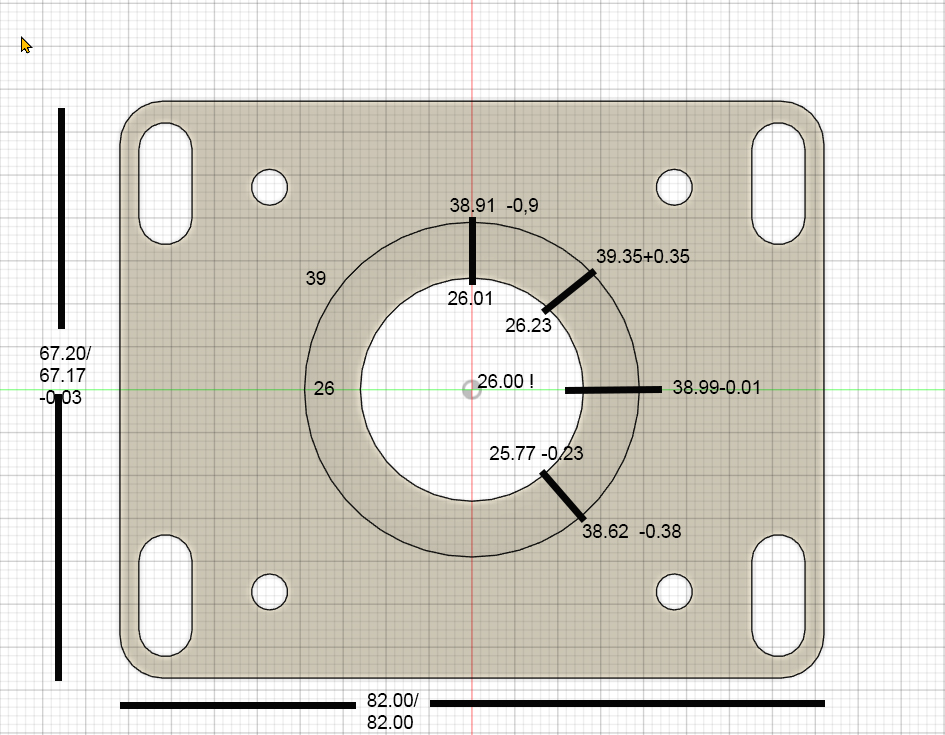
I have a Mesa 7i76e running, the wiring is correct except for the alarm loop. Using a Lenovo ThinkCentre M910q with i7 4-core, 256/GB NVMe SSD, i7 16GB RAM WLAN Intel Core i7-6700T 4x 2.80 - 3.60GHz with Linuxcnc 2.9.4, Probe Basic V.5 on Debian 12. No latency problems.
Once again, I'm here with a big problem. My DIY milling machine (1000x500x220 with aluminum profile frame, 20mm HGR, 1605 ball screws, 3 axes, 2x OMC Stpperonline 400W integrated servo, 1x JMC CL Stepper 3.5Nm, set 2000 steps/rev) is now mechanically finally assembled. I also got a lot of help from this forum in setting up LinuxCNC, eliminating latency problems and spindle control problems, but now I have a milling problem that I can't solve.
I have milled several test parts with drill holes, 2 circular pockets, and a rectangular outer contour, and have noticed that my circular pockets are becoming elliptical. The deviations in Y are approximately +0.35 mm at 45° and approximately -0.38 mm at 135°. The X values for the rectangular contour are perfect to within 0.01 mm in X and 0.09 mm in Y, X I consider to be acceptable, but Y is over tolerance. However, the circular movements contain deviations I cannot tolerate. I will show you a photo of the last test piece. After each individual test part, I made changes to rule out certain things.
The first change was to replace a simple Chinese C7 ball screw with a ground C5 spindle with double nuts. This reduced the originally even higher values by almost half. However, the deviations described above remained. After the next test part, I replaced the 400 W servo with a 3.5 Nm JMC CL stepper motor. The results remained almost the same. As a final attempt, a few days ago I replaced the spindle's fixed bearing with a new one, with 7002AC angular contact bearings in an O-arrangement with a 1 mm spacer ring between the outer rings. I inspected the previous fixed bearing and found no faults. There was a 1mm spacer also and the O arrangement was the same. I had also taken measurements at the spindle end earlier and actually and found no backlash.
Yesterday, moving away from mechanical faults, I noticed a difference in the motor definitions for the X and Y axes in the .ini file. The Ferror and min_Ferror points differed by one decimal place. X was set to 0.1 and 0.01, while the Y axis was set to 1.0 and 0.1. After I corrected this difference, the motor on the Y axis went into alarm mode after a few position changes.
What could be the reason for this? How can it be that one motor runs perfectly with much lower tolerance values, while the other quickly goes into alarm mode with less load? The motor in question has the same power supply and is certainly less demanding in terms of starting currents than the servo on the X-axis. With the higher tolerance values, the Y motor runs without alarm, but has these deviations. Are these tolerance values in the .ini file responsible for these deviations?
The mechanics of the Y and Z axes are flawless, as checked with a dial gauge, and the repeat accuracy is also very good, less than one hundredth.
Do you have any ideas about this? Where can I look further?
Thanks for your time and hints
- RotarySMP
18 Nov 2025 21:29
Replied by RotarySMP on topic Schaublin 125-CNC retrofit.
I tried
C07 --> 2. The VFD no longer started the motor.
C07 --> 1. Same behavior as CO7 - 0.
C07 --> 2. The VFD no longer started the motor.
C07 --> 1. Same behavior as CO7 - 0.
Time to create page: 0.791 seconds