- Configuring LinuxCNC
- Advanced Configuration
- Preparation for the self-construction of a carousel changer
Preparation for the self-construction of a carousel changer
- mgm
-
 Topic Author
- Offline
- Elite Member
-

Less
More
- Posts: 210
- Thank you received: 13
07 Jun 2022 19:58 #244736
by mgm
Replied by mgm on topic Preparation for the self-construction of a carousel changer
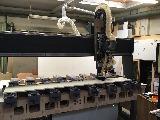
Yes, the cnc is in my workshop, I am a carpenter.
The milling machine is made of multiplex and built by myself.
The photo does not show the current status ....

The milling machine is made of multiplex and built by myself.
The photo does not show the current status ....
Attachments:
Please Log in or Create an account to join the conversation.
- spumco
- Offline
- Platinum Member
-

Less
More
- Posts: 2126
- Thank you received: 882
07 Jun 2022 23:13 #244740
by spumco
Replied by spumco on topic Preparation for the self-construction of a carousel changer
Three spindles, pneumatically gated dust extraction manifold, and what looks like automatic work stops next to the pods.
And I bet you've got one of the spindle set up just for drilling - looks like a squillion holes in that panel.
Hardly a toy is it?
Nice job mounting the top gantry rail in the correct orientation for max load capacity.
And I bet you've got one of the spindle set up just for drilling - looks like a squillion holes in that panel.
Hardly a toy is it?
Nice job mounting the top gantry rail in the correct orientation for max load capacity.
Please Log in or Create an account to join the conversation.
- mgm
-
Topic Author
- Offline
- Elite Member
-
Less
More
- Posts: 210
- Thank you received: 13
08 Jun 2022 06:46 #244753
by mgm
Replied by mgm on topic Preparation for the self-construction of a carousel changer
The machine is mainly designed for furniture making and operations that typically occur in a carpenter's workshop.
However, contrary to my initial assessment, it has turned out that an ATC brings significantly more flexibility with it, and therefore I need an ATC.
The dimensions of the components are somewhat adapted to the size!
a few data:
Working space: x = 2486 mm
y = 1150 mm
z = 285 mm
Closed Loop with 6Nm for X & Y and 12 Nm for Z
Mesa 7i76ed
Drilling spindle L & R 900W with ER11
Milling spindle (currently without ATC) 4,5 KW with ER32
later with ATC also 4,5 KW BT30 and ER32
So that I do not digress too far from the actual topic here I will soon make a separate report about the CNC.
Please Log in or Create an account to join the conversation.
- mgm
-
Topic Author
- Offline
- Elite Member
-
Less
More
- Posts: 210
- Thank you received: 13
09 Jun 2022 07:25 #244794
by mgm
Replied by mgm on topic Preparation for the self-construction of a carousel changer
Today I got the BT30 collets and the clamps. I find the collets go very tight in the clamps.
But I assume that it is normal.
Now the questions:
- I would like to bring the carousel with a cylinder in the change position. Will the cylinder hold this at 8 bar? or do I need an additional lock?
- since my x axis is quite long, I had imagined that I would let the carousel move along in a certain range. I thought between 500 and 2000 mm of the x axis. Is that still stable enough? or is there also an additional locking necessary?
The axis parallel to the x axis would be "U" right?
I can not judge what forces occur when pushing the BT30 into the brackets.
I would like your opinion on this ....
Michael
Michael
Please Log in or Create an account to join the conversation.
- spumco
- Offline
- Platinum Member
-
Less
More
- Posts: 2126
- Thank you received: 882
09 Jun 2022 11:39 #244799
by spumco
Replied by spumco on topic Preparation for the self-construction of a carousel changer
I had the same cylinder concern, but guessed and it worked out.
My cyilinder has a 32mm diameter and it easily engages the tool holders at 50-75psig. My forks are the same as used on the Tormach 1100MX, and I believe these are a bit stiffer than the typical ISO30 forks seen all over ebay and aliexpress.
As far as travel goes, this is completely up to you. And the friction of the air cylinder, rails, and cable chain should keep it in place when not engaged. I don't see the need for an extra lock, although a small ball detent at the travel ends wouldn't hurt in case it starts creeping during vibration.
There's enough friction in my system it simply won't move unless air is supplied to the cylinder. I'm using a rodless cylinder with built-in rails that has fairly high starting friction, but you may be using the more typical separate slides & cylinder arrangement. (Or even a pivot).
Don't forget to install pneumatic speed valves for both directions of carousel travel. Must have a way of slowing down the engagement - pneumatics can be dangerous.
Please Log in or Create an account to join the conversation.
- mgm
-
Topic Author
- Offline
- Elite Member
-
Less
More
- Posts: 210
- Thank you received: 13
09 Jun 2022 17:08 #244808
by mgm
Replied by mgm on topic Preparation for the self-construction of a carousel changer
That does sound good to me.
Then I will continue as planned.
Yes, nothing works with pneumatics without throttle valves!
Then I will continue as planned.
Yes, nothing works with pneumatics without throttle valves!
Please Log in or Create an account to join the conversation.
- mgm
-
Topic Author
- Offline
- Elite Member
-
Less
More
- Posts: 210
- Thank you received: 13
12 Jun 2022 18:26 #245013
by mgm
Replied by mgm on topic Preparation for the self-construction of a carousel changer
A little further up I had already briefly mentioned the idea of a carousel.
Before I get completely lost in the thoughts I would like to have an assessment from you regarding the feasibility.
I have thought about it as follows:
First variant
At the positive end of the y-axis attach an additional axis "U" which is parallel to the x-axis.
This u-axis is 500mm shorter on both sides than the x-axis, which is 2486mm long.
The carousel is then mounted on "u".
If x moves further than 500 mm, u moves with it until 500 mm before the end of x, then u stops again.
I hope I have expressed this understandably?
So the way to the change position would be relatively short.
Alternatively
There are two fixed change positions
If x is between 0-1200 mm pos 1 and between 1250 -2486 is pos 2
Second alternative
This idea is pure fantasy of me!
When a program is loaded, a preview is created. Does the interpreter already know in the preview at which coordinate the tool change takes place?
If yes, one could send the changer at the beginning of the program parallel to the execution of the g code already to the position.
Are these considerations totally stupid or could something like this be implemented.
I think the alternative is feasible in the remap. There is only the question whether this saves time.
I ask for comments and objections
Please Log in or Create an account to join the conversation.
- spumco
- Offline
- Platinum Member
-
Less
More
- Posts: 2126
- Thank you received: 882
12 Jun 2022 19:30 #245020
by spumco
Replied by spumco on topic Preparation for the self-construction of a carousel changer
I've seen a few different tool changers for gantry machines.
1. Head-mounted. This was on a commercial router, and the 6-tool changer was mounted on a sliding frame which was attached to the front of the head. Added weight to the head, of course, but probably the fastest tool changer. Think of a Robodrill or Brother speedio, except the tools were on a horizontal disc and not a big radial wheel.
2. Gantry mounted, fixed. Basically a carousel mounted at the end of the gantry. Head would move over to it for tool changes, carousel was outboard of the working area.
3. Gantry mounted, pivoting. Same as above, but the carousel was on a pivot so it was stowed behind the gantry between tool changes.
4. Table mounted at back of machine, fixed position. Very much like a rack changer, except the head only goes to one toolchange position and the carousel takes care of tool selection. Slowest due to the travel time, but had the possibility of the most tools. The one I've seen was a simple disc tool holder with about 10 tools, but a huge oval chain-drive thing could have been fabricated to hold a LOT of tools. For a 4' wide table, you could probably get 50 or more tools on a big oval.
Questions to ask yourself:
How many tools do you expect to use in a job?
How big are your tools, and how big will your carousel need to be?
Do you plan on using the tool changer as tool storage (to save setups & touchoffs for different jobs)
How important is tool change speed?
If you have 5 tool changes per job, can you live with 30 seconds per tool change? Or do you need 5 seconds because you're changing tools 30 times per job?
I'm suggesting these questions because a fixed-position, table-mounted carousel is probably the easiest to implement and integrate in to your machine. But comes with a slow toolchange price.
Please Log in or Create an account to join the conversation.
- mgm
-
Topic Author
- Offline
- Elite Member
-
Less
More
- Posts: 210
- Thank you received: 13
13 Jun 2022 04:35 #245052
by mgm
Replied by mgm on topic Preparation for the self-construction of a carousel changer
When making cabinet components, I actually only need 1-3 tools per part. For one side of the cabinet, I can manage without changing the main spindle. Since I still have the two small drilling spindles on the left and right side and these are pneumatically retracted and extended.
When it comes to the front, I need a changer for the main spindle.
The changer should stock the tools that are frequently needed. The changer has 12 places and a diameter of approx. 500 mm (20 inches).
Since I always have to produce left and right parts during production, the way to the changer can be long, hence my consideration.
This could be a distance up to 1800 mm (70 inches) depending on the position of the changer.
The carousel is located outside the working area and is brought into the travel range of the machine during the change.
The easiest would be of course to mount the changer in the middle of the x axis.
And you are right, that would be the simplest variant, but one or the other variant would be challenging. But that will certainly exceed my possibilities in terms of programming. Is there perhaps already a component in this regard?
I would need for a more complicated variant certainly the help here in the forum.
Please Log in or Create an account to join the conversation.
- andypugh
-

- Offline
- Moderator
-

Less
More
- Posts: 19886
- Thank you received: 4645
15 Jun 2022 11:20 #245184
by andypugh
Replied by andypugh on topic Preparation for the self-construction of a carousel changer
One common solution is to use a G-code remap to position the axes and the changer, and the carousel component to present the correct tool to the spindle.
To this end, you could certainly arrange for the subroutine to calculate a place for the U and X to "meet in the middle".
I am not sure how useful that would be, but it would be cool to watch.
Otherwise, pre-positioning the changer could be handled by a script that adds a positioning move for the changer to the G-code. LinuxCNC can automatically run this script as a filter when the G-code file is loaded.
Please Log in or Create an account to join the conversation.
- Configuring LinuxCNC
- Advanced Configuration
- Preparation for the self-construction of a carousel changer
Time to create page: 0.124 seconds