Dual PID loops with motor encoder + scale encoder per axis

More
2 years 5 months ago #299570 by TangentAudio

I don't think your home switch will work. Home switches need to stay triggered until the end of travel. This lets Linuxcnc which direction to travel to find the triggering edge. I predict some big crashes under the current config.
I had some time at lunch today, so I wired up the switches to my temporary control breadboard.  The left switch is configured as both X- limit and home, and the "disable limits while homing" option is set in my ini.

When not homing, both switches act as limits and will e-stop LinuxCNC, which I have tested but did not demo in the video.  I have the soft limits set correctly so it stops before tripping the limit when jogging.


cheers,
Steve

Please Log in or Create an account to join the conversation.

More
2 years 5 months ago #299572 by Tinine
Well to take it to an extreme, as an example. What happens when to lock a rotor of a motor and switch on the power? You are slowing the motor down and therefore reducing the back-EMF.

Craig

Please Log in or Create an account to join the conversation.

More
2 years 5 months ago #299579 by rodw

Hi Rod,
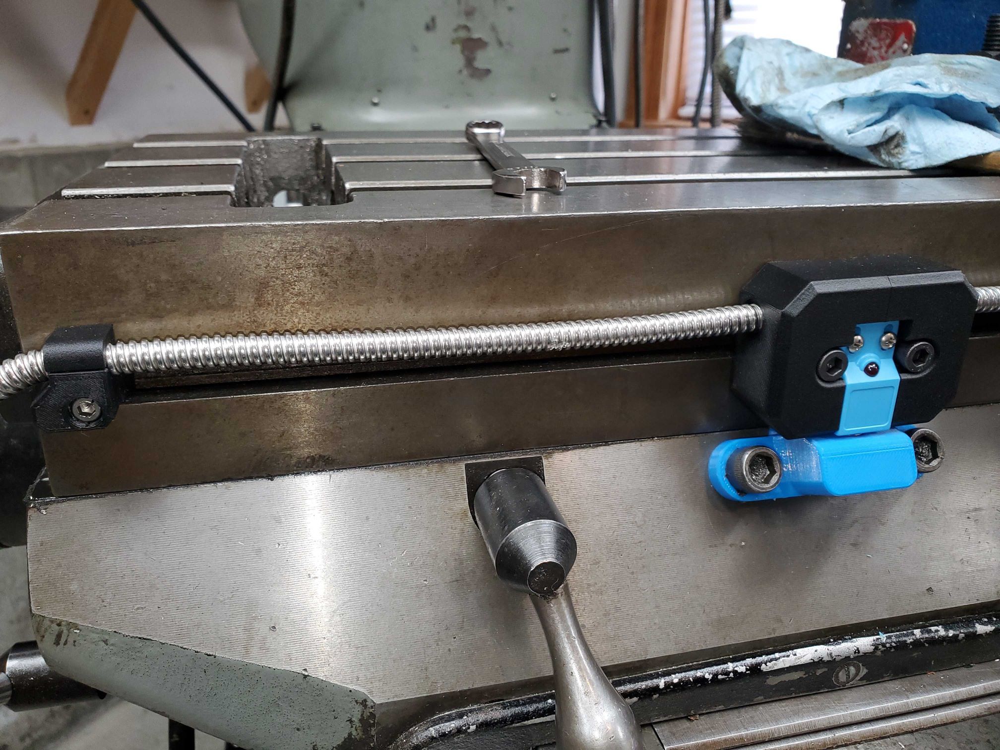
Unless I'm missing something, I'm not sure I follow your concern. The switches are located at the end of travel on each end of the table. They stay active for at least 10mm of table travel beyond their initial trigger point. They're positioned as limit switches really, but I should be able to home off of the left one as well.
Forget useable travel.
For homing, The machine cannot be allowed to be positioned on either side of the home switch and the switch be off in both these positions. It must be set up so it is on on one side and off on the other side of the home trigger point. This lets Linuxcnc know where it is in relation to the home switch. I learnt the hard way.

Please read homing configuration in the docs until you understand this.  linuxcnc.org/docs/stable/html/config/ini-homing.html

If using a separate homing switch, it is possible to start homing on the wrong side of the home switch, which combined with HOME_IGNORE_LIMITS option will lead to a hard crash.
 

Please Log in or Create an account to join the conversation.
More
2 years 5 months ago #299581 by TangentAudio

Forget useable travel.
For homing, The machine cannot be allowed to be positioned on either side of the home switch and the switch be off in both these positions. It must be set up so it is on on one side and off on the other side of the home trigger point. This lets Linuxcnc know where it is in relation to the home switch. I learnt the hard way.

Please read homing configuration in the docs until you understand this.  linuxcnc.org/docs/stable/html/config/ini-homing.html

If using a separate homing switch, it is possible to start homing on the wrong side of the home switch, which combined with HOME_IGNORE_LIMITS option will lead to a hard crash.

Rod, it is not possible to start homing on the wrong side of the home/limit switch in my setup.  The limit switch (left switch) is at the physical limit of where the table can travel due to a mechanical interference between the motor mount and saddle.  This is what I mean by usable travel.  In the photos I posted, it may look like the table can travel more in the X- direction beyond the switch, but it can't.

I really do appreciate the heads up (I'm not immune to dumb mistakes by any means), but just for the record, I have been using LinuxCNC for about 15 years and I'm not a stranger to how it handles homing.

cheers,
Steve
The following user(s) said Thank You: rodw

Please Log in or Create an account to join the conversation.
More
2 years 5 months ago #299586 by TangentAudio
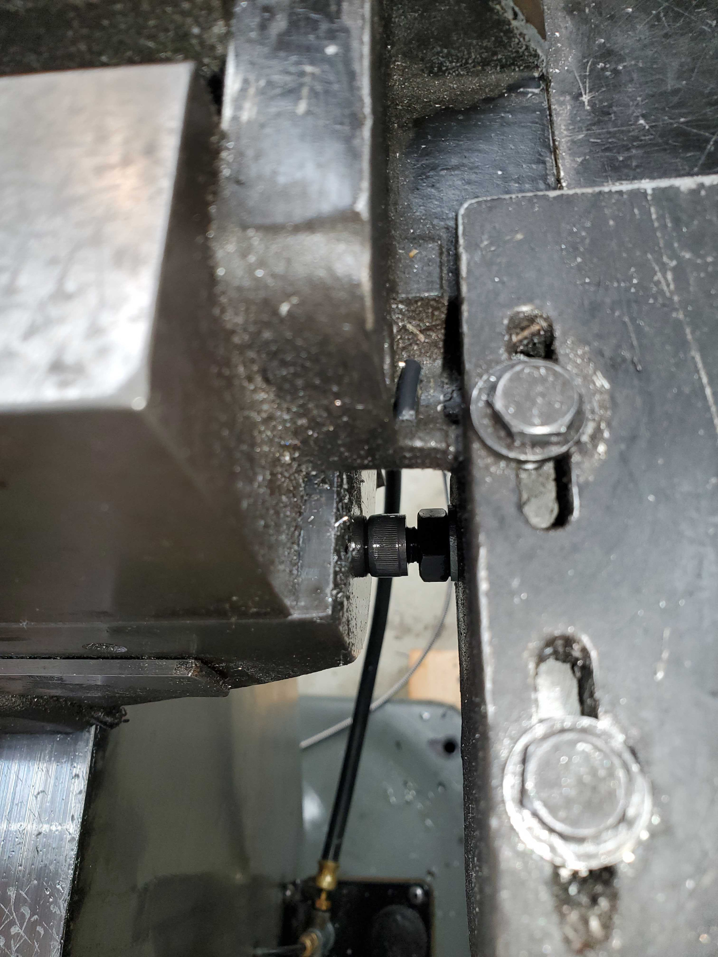
I couldn't find a good camera angle that shows everything at once, but there's a jackscrew on the back of the motor mount that sets a hard limit.  This physical stop is about 1/4" beyond where my home switch actually triggers, but even when it's parked right at the hard limit, the home/limit switch is still active.  Power was off when I took these photos, so the sensor LED is not on, but you'll get the point.

Hopefully this clears it up.

cheers,
Steve


Please Log in or Create an account to join the conversation.
More
2 years 5 months ago #299945 by TangentAudio
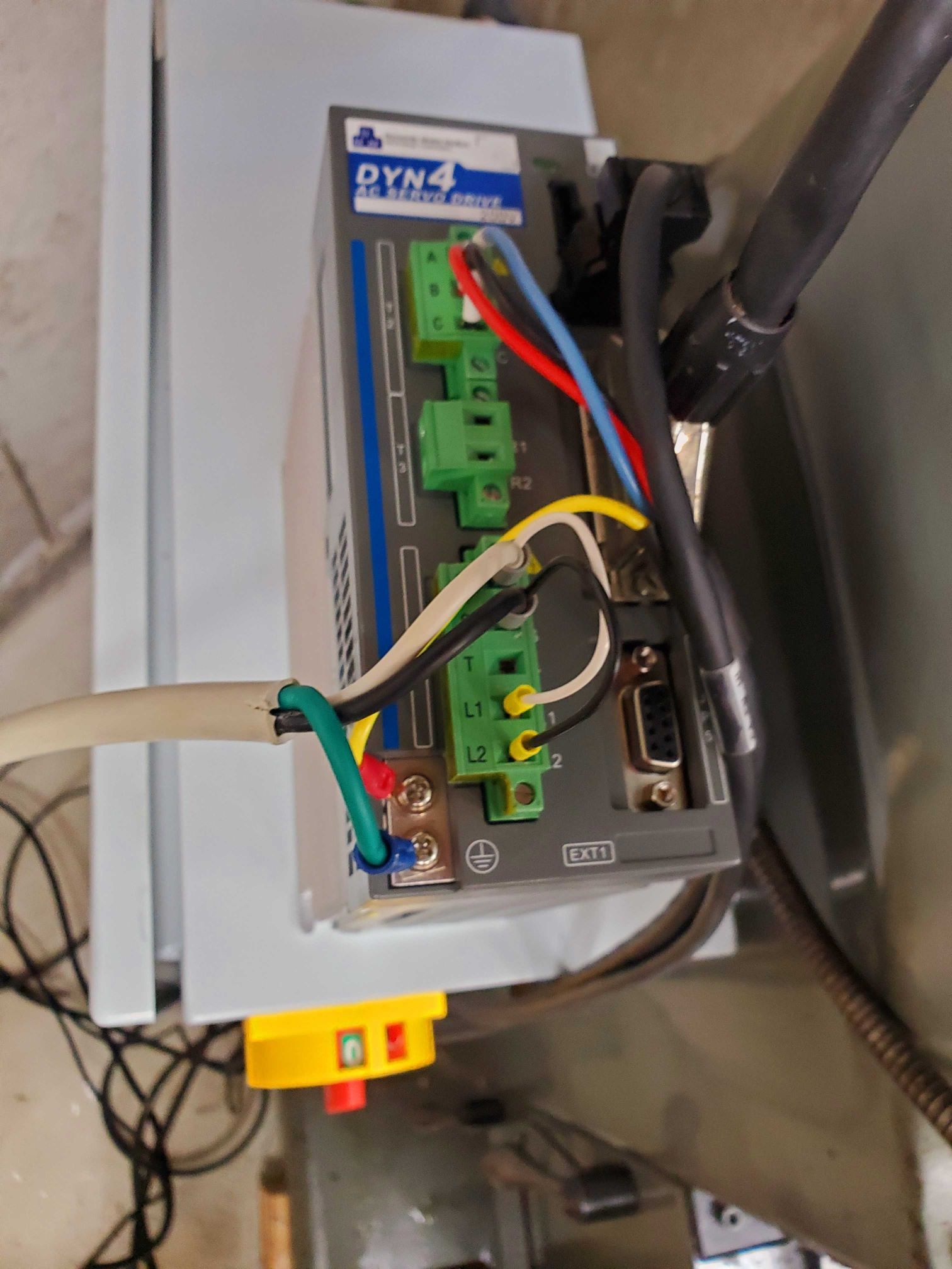
I was lucky to stumble into a DMM DYN4 750W AC servo and drive for free, so this gives me a good opportunity to test a modern setup on one axis. 

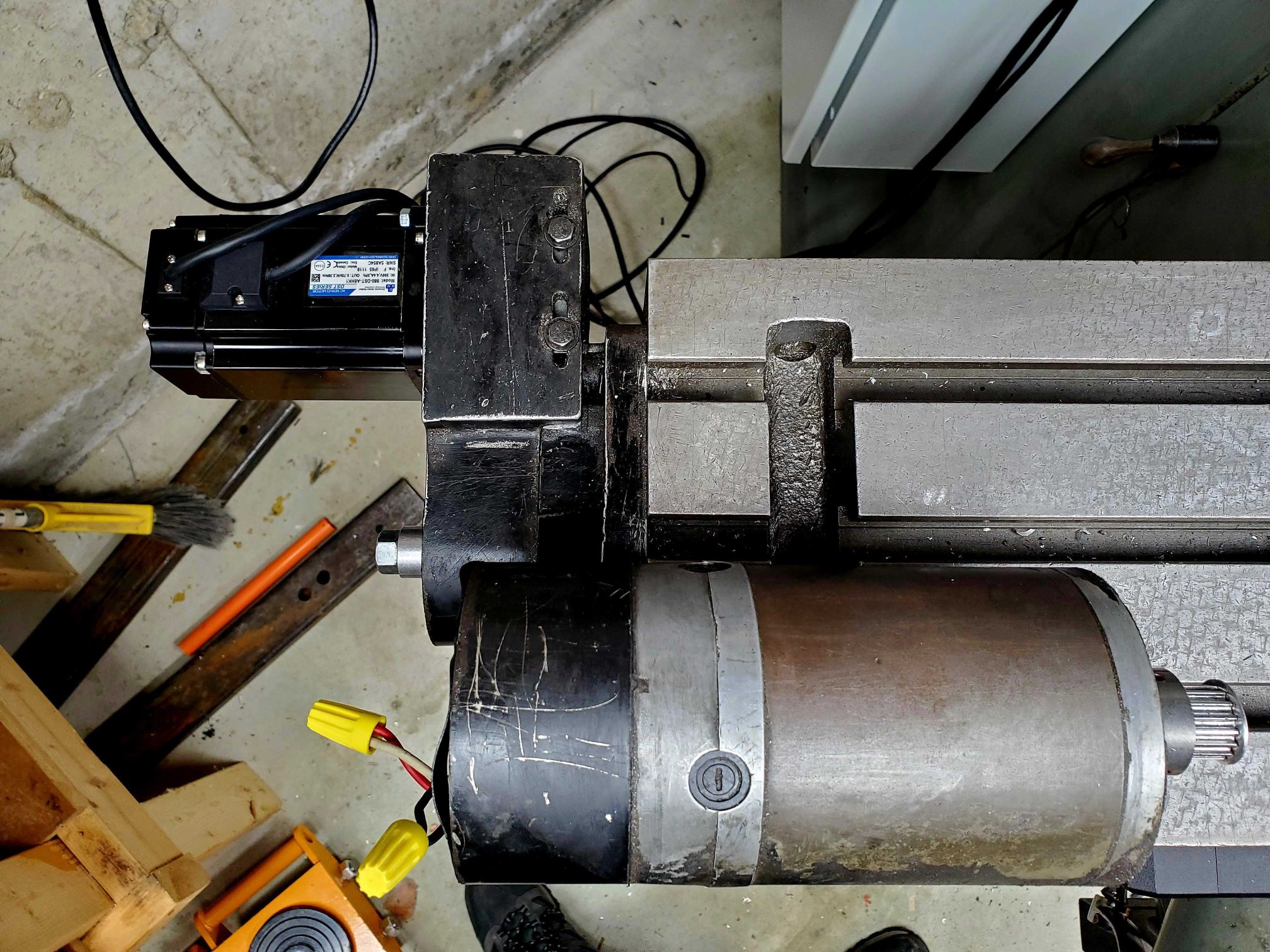
I was able to temporarily mount the 80 frame motor into the same mount as the original brushed DC motor, though only two bolt holes align in the motor slots - good enough for testing, but I'll have to modify the mount if this becomes a permanent thing.  For testing, I 3D printed a custom Gates HTD 5M 17T pulley for the AC servo's much larger 19mm shaft, as there's no off-the-shelf availability with exactly the right combination of bore, keyway, and tooth count. 


I've got the drive wired up in step/dir mode as I don't have any +/-10V output options on my bench test breadboard at the moment.


Using the DMM tuning software, I was able to put a quick auto-tune on it, and I've got it moving around under LinuxCNC control using position control from a stepgen in the Mesa.  It sure seems to move the heavy table with an extra 100lbs on it like it's nothing, at some pretty absurd rapids (350+ inch/minute). 

I need to decide if I'm going to either build or buy a means of getting +/-10V output so I could try running the drive in torque or velocity mode.  With step/dir I'm limited to position mode, or faking velocity mode using the stepgen velocity output mode.

I also have not yet wired up the drive's encoder outputs, but they are available on the 9 pin connector on the drive.  That will be necessary to play with velocity or torque mode.


The following user(s) said Thank You: besriworld

Please Log in or Create an account to join the conversation.
Time to create page: 0.076 seconds
Powered by Kunena Forum
